Hot Keywords:
- All
- Product Name
- Product Keyword
- Product Model
- Product Summary
- Product Description
- Multi Field Search

Views: 0 Author: Welldone power Publish Time: 2026-11-13 Origin: Site


An amorphous-core transformer cuts no-load loss to about one-third of a grain-oriented silicon-steel unit — a 60–80% drop. The gain comes from a 25-micron iron ribbon frozen at ≈10⁶ °C/s so it never crystallizes. The trade-offs in noise, short-circuit strength, and cost must be priced in before you specify.
No-load loss (often called iron loss or core loss) is the power a transformer draws to maintain its magnetic field with the secondary open. It is consumed 24/7, whether the unit carries load or not. For a distribution transformer that sits energized but lightly loaded for most of its life, no-load loss is a large share of the lifetime energy bill. That is precisely why the material the core is made from matters more than the copper on the windings: iron loss is set by the core steel, and it never switches off.
Conventional cores use grain-oriented silicon steel (CRGO) — a crystalline alloy engineered so its grains align the easy-magnetization direction along the strip. Amorphous alloy removes the crystals entirely.
The defining fact of amorphous metal is the quench rate. Molten iron–silicon–boron alloy (typically Fe–Si–B, with nanocrystalline variants adding Cu and Nb) is poured onto a rapidly spinning cooled wheel — melt spinning — and cooled at roughly 10⁶ °C per second. At that rate the atoms have no time to arrange into a crystal lattice; they are locked into a random, glass-like (amorphous) structure. The result is a ribbon about 20–30 microns thick, usually cited near 25 microns — roughly one-fifth the thickness of a grain-oriented steel lamination — supplied in wide coils by specialist mills (a common commercial grade is Metglas 2605SA1).
Two structural consequences drive everything that follows. First, with no crystal grains and no grain boundaries, there are almost no domain-wall pinning sites, so the magnetic domains flip with far less energy — that is the source of the low loss. Second, the material is, structurally, a frozen liquid: hard and brittle like glass rather than ductile like steel.
Measured specific loss for amorphous ribbon at typical operating flux (1.3–1.5 T, 50/60 Hz) runs about 0.20–0.30 W/kg, against 0.85–1.0 W/kg for CRGO. Translated to a finished core, that is a no-load loss roughly 60–80% below a silicon-steel design of the same rating — the single figure that justifies the whole technology.
The mechanism is eddy currents. Core loss has two parts: hysteresis (the work of flipping domains) and eddy-current loss (circulating currents induced in the steel itself). Amorphous ribbon wins on both, but the eddy-current side is the clearest physics story: eddy loss scales with lamination thickness squared, so at ~25 microns the ribbon is 6–8× thinner than CRGO's ~150–200 microns, slashing the eddy component directly. Its resistivity (~130 µΩ·cm vs ~45–50 µΩ·cm for silicon steel) is also higher, which further suppresses circulating currents. The combination — thin, resistive, and domain-friendly — is why the iron loss collapses.
The same glassy structure that kills the loss creates problems a design engineer has to solve. Five matter most.
1. Lower saturation flux density → a physically bigger core. Amorphous alloy saturates near 1.56 T, against ~2.0 T for CRGO. To carry the same voltage and frequency at a safe flux density, you need more cross-sectional area — typically 30–40% more core volume for the same kVA. The transformer gets heavier and larger for the same rating.
2. Higher magnetostriction → more noise. Magnetostriction is the tiny physical stretching a magnetic material does as it magnetizes; it is what makes a transformer hum. Amorphous ribbon sits around 27–30 ppm, versus 3–7 ppm for CRGO — roughly an order of magnitude higher. In practice that puts audible noise 5–8 dB(A) above an equivalent silicon-steel unit. In a residential or indoor location this single property can decide whether the unit is acceptable.
3. High hardness and brittleness → handling and assembly risk. Vickers hardness of amorphous ribbon is approximately 860–1100 HV, against ~150–250 HV for silicon steel; fracture toughness is around 1 MPa√m versus ~50. The ribbon is essentially a frozen glass: it cracks rather than bends. Cutting, stacking, and clamping must avoid sharp bends and point loads, and the core cannot be punched like steel laminations.
4. Stress sensitivity → the clamping paradox. This is the most counter-intuitive property. Mechanical stress on the ribbon degrades its magnetic properties; clamp an amorphous core too tightly and no-load loss can roughly double. The engineering answer is a floating or loosely-tensioned core structure that supports the stack without squeezing the ribbons — a different mechanical design than a silicon-steel core receives.
5. Lower space factor → more material for the window. The lamination (stacking) factor of amorphous ribbon is about 0.85–0.87, against ~0.96 for CRGO. More of the core volume is gaps, so for a given magnetic cross-section you again need more material. This compounds the size penalty from point 1.
Property | Amorphous alloy | Grain-oriented Si steel (CRGO) | Engineering consequence |
Specific loss @1.3–1.5 T, 50 Hz | 0.20–0.30 W/kg | 0.85–1.0 W/kg | 60–80% lower no-load loss |
Saturation flux density Bs | ~1.56 T | ~2.0 T | ~30–40% larger core for same kVA |
Magnetostriction | 27–30 ppm | 3–7 ppm | Audible noise +5–8 dB(A) |
Vickers hardness | 860–1100 HV | 150–250 HV | Brittle; cannot be punched |
Fracture toughness | ~1 MPa√m | ~50 MPa√m | Cracks, does not bend |
Resistivity | ~130 µΩ·cm | ~45–50 µΩ·cm | Lower eddy loss |
Stacking factor | 0.85–0.87 | ~0.96 | More core material needed |
Material cost | ~1.3–1.6× Si steel | baseline | Premium recovered only via TCO |
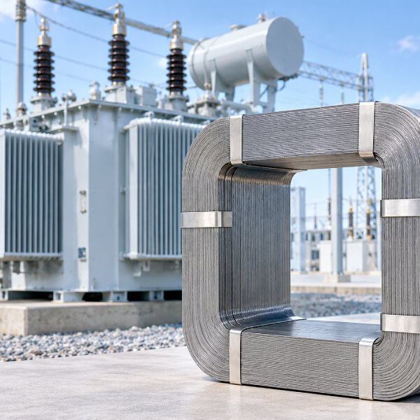
Because the core is built from thin, brittle ribbons rather than rigid laminations, an amorphous-core transformer generally shows weaker short-circuit withstanding than its silicon-steel counterpart. The ribbons offer less mechanical rigidity, and the winding-to-core bracing has to be designed around the brittle material rather than assuming the core itself contributes stiffness. For a distribution unit this is manageable with proper winding support and bracing — but it must be designed for, not assumed away. A specifier comparing an amorphous unit against a conventional one should ask specifically how short-circuit force is carried, because the headline loss number says nothing about it. Amorphous cores also draw a somewhat higher magnetizing (excitation) current than CRGO, a secondary point worth noting in any side-by-side.
No-load loss is a 24/7 draw, so its value depends on the load factor — the ratio of average load to peak. Two rules of thumb:
Low and variable load → strong payback. Street-lighting transformers, rural distribution feeders, and public-area units that sit energized but lightly loaded for most hours recover the material premium fastest. Typical simple-payback analyses land in the 2.5–7 year range depending on energy price and load profile.
Distributed PV and storage interfaces that hold the transformer energized for voltage support even when local load is low are another natural fit, because the unit earns its keep on iron-loss reduction during all those idle hours.
The purchasing lever is loss capitalization (the "capitalized cost of losses" used in many utility tender frameworks, e.g. IEEE C57.120): the buyer assigns a monetary value to no-load and load loss, and the amorphous unit's lower no-load loss is worth more the higher that value and the longer the energized hours. Material cost itself runs about 1.3–1.6× silicon steel, so the economics hinge on that capitalized-loss math, not on sticker price.
State the no-load-loss target, not just the material. Ask for a guaranteed no-load loss figure (often per IEC 60076 efficiency class or a specific W value) so the supplier cannot meet "amorphous" on paper while delivering a loose core that has lost its advantage to clamping stress.
Cap the audible-noise level explicitly. Require a dB(A) limit at rated voltage (and specify the measurement distance), because the magnetostriction penalty is real; ask what acoustic treatment or enclosure the design uses to meet it.
Demand a short-circuit withstand statement. Require IEC 60076 short-circuit test compliance and a description of how the brittle core is braced — do not let the loss number stand in for it.
Ask how clamping stress is controlled. Require the core to be built as a floating or low-tension structure so no-load loss is not degraded in assembly; a credible supplier states this as a design feature.
Specify the ribbon grade and source traceability (e.g. IEC 60404-6 ring-sample loss test, IEC 60404-8-6 for strip), so the quoted loss is tied to a verifiable material specification rather than a marketing claim.
Run the TCO, not the sticker. Use loss-capitalization math (IEEE C57.120 basis) over the expected load profile and energized hours; for low-load-factor sites the amorphous unit usually wins, for high and steady load it may not.
Dimension | Grain-oriented Si steel | Amorphous-core | What it means for the specifier |
No-load loss | Baseline | 60–80% lower | Main reason to choose amorphous |
Core size / weight | Baseline | ~30–40% larger | Space and handling allowance |
Audible noise | Baseline | +5–8 dB(A) | Noise limit & enclosure needed |
Short-circuit stiffness | Higher | Lower (brittle ribbons) | Bracing must be designed for |
Clamping tolerance | Robust | Stress-sensitive (loss can double) | Floating-core construction required |
Best-fit duty | Steady, high load | Low / variable load factor | Drives the TCO case |
Q: How much no-load loss does an amorphous core actually save?A: Roughly 60–80% below a grain-oriented silicon-steel core of the same rating — finished-core specific loss around 0.20–0.30 W/kg versus 0.85–1.0 W/kg. The exact saving depends on design flux density and frequency, but the order of magnitude is the reason the technology exists.
Q: Why is an amorphous transformer noisier?A: The ribbon's magnetostriction is about 27–30 ppm versus 3–7 ppm for silicon steel — roughly ten times the physical stretching as it magnetizes — which raises audible noise by roughly 5–8 dB(A). Acoustic enclosure or a lower design flux is how the penalty is managed.
Q: Is an amorphous-core transformer weaker against short circuits?A: Generally yes, relatively. The core is built from thin brittle ribbons rather than rigid laminations, so it contributes less mechanical stiffness, and winding bracing must be designed around that. It is manageable with proper support, but it must be specified and tested (IEC 60076), not assumed.
Q: When does the higher material cost pay back?A: On low and variable load factors — rural feeders, street lighting, public-area units, and PV/storage interfaces that stay energized for voltage support. Simple payback commonly falls in the 2.5–7 year band; the rigorous test is loss-capitalization math over the actual load profile (IEEE C57.120).
Q: What should I write into the specification to protect the loss advantage?A: A guaranteed no-load-loss figure (not just "amorphous"), an explicit dB(A) noise limit, a short-circuit withstand statement with bracing description, evidence that the core is built floating or low-tension to avoid clamping-stress loss growth, and a ribbon-grade reference (IEC 60404-6 / 60404-8-6).
An amorphous-core transformer is not a "better silicon-steel transformer"; it is a different material bet. You trade a 25-micron glassy ribbon's extraordinary low loss — 60–80% below conventional iron — for a bigger, noisier, more brittle, stress-sensitive and costlier core that must be braced and clamped differently. The win is real and large wherever no-load loss dominates the bill: low-load-factor distribution, rural and public-area service, and PV/storage interfaces. The loss number alone never tells you that, which is why a specification has to name the noise limit, the short-circuit bracing, and the floating-core construction explicitly — and why the buying decision belongs in a total-cost-of-ownership calculation, not a sticker-price comparison.
