Hot Keywords:
- All
- Product Name
- Product Keyword
- Product Model
- Product Summary
- Product Description
- Multi Field Search

Views: 0 Author: Welldone power Publish Time: 2026-11-05 Origin: Site


A dry-type transformer in salt-fog offshore service degrades on a predictable clock — surface contamination, lost hydrophobicity, internal moisture, creeping partial discharge. Every one of those failures is detectable months ahead with online monitoring. The catch: inspection needs a vessel, so monitoring has to replace the calendar.
Onshore, a transformer is a walk-up asset. An electrician checks it on a calendar, thermographs it during a planned outage, and the worst-case cost of a missed inspection is a truck roll. Offshore, that model collapses. Reaching a nacelle or a platform transformer means a vessel, a weather window, a crew, and a lift — a single intervention that can cost more than the component it services. When access is that expensive, the maintenance question inverts: instead of asking "when should we go look?", the engineering ask becomes "what can we know without going?"
That is the entire justification for condition-based maintenance (CBM) on offshore dry-type transformers, and for reliability-centered maintenance (RCM) that treats the vessel trip as the dominant cost in every decision. The design measures covered in the companion piece on offshore dry-type design — extended creepage, hydrophobic coatings, sealing, a chosen cooling architecture — set the starting point and the rate of degradation. Monitoring is what tells you whether that design is still holding, and gives you lead time to act before a fault. The two are sequential, not alternatives.
A dry-type transformer has no oil, so the single most powerful diagnostic used on liquid-filled units — dissolved-gas analysis (DGA) — simply does not exist here. The signal set has to be rebuilt around what dry-type degradation actually does. Five instruments earn their place.
1. Online partial discharge (PD) — the highest-value signal. Salt fog drives surface conductivity and tracking along the creepage path, and partial discharge is the earliest electrical signature of that process. PD is measured to IEC 60270; in practice offshore dry-type units are fitted with high-frequency current transformers (HFCT) on the earth connection, often covering a 500 kHz–50 MHz band and resolving discharges down to roughly 10 pC, plus ultrasonic sensors that pick up the surface-tracking "hiss" before it becomes a flashover. The point is not the absolute number on day one — it is the trend. A clean winding trends flat; a winding under salt attack shows a rising PD magnitude and an increasing rate of discharge events. That rise typically precedes a fault by months.
2. Internal humidity and dew-point. The enemy inside a sealed enclosure is not the salt you kept out, but the moisture you trapped in. RH and dew-point sensors inside the transformer compartment, paired with heater-duty logging and desiccant status, tell you whether the anti-condensation strategy from commissioning is still working or whether the enclosure has started breathing contaminated air. When internal RH climbs toward the dew point at the winding surface, you are watching the same insulation wet-out that kills the unit — from the inside.
3. Winding and hotspot temperature vs load. Pt100 elements or fiber-optic sensors on the winding, trended against the actual load profile, expose two things: whether the cooling architecture is losing margin (fouled heat exchanger, failing fan, blocked filter), and whether the unit is being loaded harder than its thermal design assumed. A load–temperature curve that steepens over a year is an early warning the cooling path is degrading — exactly the failure the design tried to prevent.
4. Insulation resistance (IR) and polarization index, trended. Periodic Megger testing (typically 2.5–5 kV DC for distribution-class dry-type) stays useful offshore, but the rule is trend, not snapshot. A single IR value means little without temperature correction and a baseline; a falling IR trend across accessible windows is the confirmation that surface or internal moisture is accumulating. The measurement is periodic because it needs a safe access window — which is precisely why the continuous signals above have to carry the day-to-day load.
5. Vibration trending. The mechanical environment — rotor harmonics, tower sway, yaw transients — loosens tie-downs and terminations over millions of cycles. Accelerometers on the transformer structure, trended rather than merely alarmed, show the slow creep of a fastener or a brace that has started to work. This is the same fatigue mechanism that the design tried to bolt out, now watched in service.
The hydrophobic (RTV/silicone) coating on the winding is what breaks the electrolyte bridge that salt fog would otherwise form. Its performance does not follow a calendar; it follows exposure. The correct way to judge it is the hydrophobicity classification of IEC TS 62073: HC1 is a surface that sheds water into discrete beads (fully hydrophobic), and the scale runs to HC7, a continuous water film — effectively hydrophilic and doing nothing to stop tracking. A CIGRE study of in-service composite insulators estimated the average unit drifts toward HC6 after roughly 10–25 years. For a transformer coating under constant marine exposure, the re-coat decision should be keyed to that measured class, not to a fixed interval: when the coating trends toward HC5–HC6, plan the re-coat into the next accessible window. Spray testing on site is cheap and fast; the expensive part is only the re-coat itself, and that should be timed by evidence.
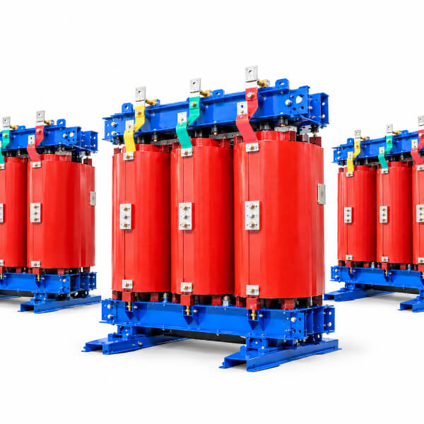
Condition monitoring is only valuable if it changes a decision. The useful pattern to teach the shore-side team is the convergence of three leading indicators, each of which is individually survivable but collectively a forecast:
Rising PD magnitude and event rate — the surface is breaking down.
Falling hydrophobicity class (HC climbing toward HC6) — the coating that was suppressing that breakdown is gone.
Rising internal RH / dew-point approach at the winding — moisture is now available to complete the path.
Any one of these warrants attention. All three, trending together, mean a flashover or winding fault is no longer a question of if but of when — and that "when" is usually far enough out to schedule a vessel trip on your terms rather than answer an alarm at 3 a.m. in a storm.
The mistake is to write an offshore maintenance plan like an onshore one and then discover the access cost dominates every line. A plan that survives contact with reality does five things:
Defaults to CBM. Inspect and intervene on trend, not calendar. The calendar still governs the periodic measurements (IR, hydrophobicity spot-check) that need a human, but the continuous signals set the alarm.
Owns the data. One system — typically fed to shore over IEC 61400-25 or a MODBUS link — with defined alarm thresholds and a named owner. A PD trend that nobody trending is worse than no PD sensor.
Stocks the right spares. Heater elements, desiccant cartridges, an RTV re-coat kit, and spare sensor modules, sized to the vessel-trip frequency rather than to a generic bill of materials. The spare you do not have becomes another voyage.
Pre-stages work. Bundle every intervention into the same access window: if you are going out for a re-coat, you also do the IR test, the sensor check, and the desiccant swap. One trip, all the work.
Feeds a fleet model. Per-turbine trends across a wind farm teach the next design iteration — which is where ISO 55000 asset-management discipline turns monitoring from a cost into a learning loop.
Dimension | Time-based (onshore habit) | Condition-based (offshore reality) |
Inspection trigger | Calendar / running hours | Trend crossing a threshold |
Access assumption | Walk up to it | Vessel + weather window + crew |
Primary signal | Visual + periodic thermography | Online PD + RH/dew-point + temp trends |
Coating decision | Re-coat on schedule | Re-coat on measured HC class (IEC TS 62073) |
Failure warning | Often none until the trip | Months of leading indicators |
Cost model | Low access cost | Vessel-trip cost dominates every decision |
Require sensor provisions at purchase — HFCT PD sensors, internal RH/dew-point, winding temperature, and vibration — not as a retrofit afterthought. A unit not built to be watched will be expensive to watch later.
Mandate IEC 60270-calibrated PD with trend logging and a written alarm philosophy (magnitude and rate-of-rise), so the shore team knows what "bad" looks like before it happens.
Make hydrophobicity tracking (IEC TS 62073 HC class) the re-coat trigger, not a fixed interval, and require the coating system to be field-re-coatable.
Specify shore-side integration (IEC 61400-25 / MODBUS) with alarm thresholds and a single named data owner, so the signals are acted on.
Define the spares strategy — heater elements, desiccant, RTV re-coat kit, sensor modules — sized to vessel-trip frequency, not to a generic parts list.
Adopt CBM/RCM in the O&M contract with the vessel-trip cost explicit in every intervention decision; intervene when the trends say so, not when the calendar says so.
Q: Can't we just inspect offshore transformers on a calendar like we do onshore?A: No. Access is a vessel, a weather window, and a crew; a "check every six months" becomes a string of expensive trips that can still miss a fault developing between them. Continuous online monitoring gives signals every day and replaces routine visual checks — the vessel goes out when the data says to, not on a date.
Q: What is the single most valuable online signal for a dry-type unit?A: Partial discharge. A dry-type transformer has no oil, so dissolved-gas analysis — the workhorse diagnostic for liquid-filled units — does not apply. PD, measured to IEC 60270 and often with HFCT sensors at around 10 pC sensitivity, is the earliest indicator of the surface-tracking and creepage degradation that salt fog drives.
Q: How do we decide when to re-coat the hydrophobic (RTV) layer?A: By measured hydrophobicity class (IEC TS 62073: HC1 fully hydrophobic to HC7 continuous film), not a fixed schedule. A CIGRE study estimates the average composite insulator drifts toward HC6 — effectively hydrophilic — after 10–25 years; when the winding coating trends that way, plan the re-coat into the next accessible window.
Q: Does monitoring remove the need for the design measures in the offshore design article?A: No. Design — extended creepage, hydrophobic coating, sealing, a chosen cooling architecture — sets the starting point and the degradation rate. Monitoring verifies the design is still holding and buys lead time to act. The two are sequential, not alternatives.
Q: What data should actually reach the shore?A: PD magnitude and trend, internal RH/dew-point and heater duty, winding hotspot temperature against load, periodic insulation-resistance trend, and vibration trend — each with thresholds and a named owner, fed to a shore-side dashboard so a fault is predicted rather than discovered.
Offshore dry-type transformers do not fail by surprise; they fail by neglect of the signals that precede failure. With no oil to analyze, the monitoring set is rebuilt around partial discharge, internal humidity, winding temperature, insulation-resistance trend, and vibration — and around a hydrophobicity class that tells you when the coating has stopped protecting the surface. The whole point of the investment is to convert an unpredictable, storm-time failure into a scheduled, your-terms vessel trip. A unit watched this way is not a cheaper unit; it is a unit whose thirty-year life at sea you can actually predict, and whose failures you meet on a calendar of your choosing rather than the weather's.


