Hot Keywords:
- All
- Product Name
- Product Keyword
- Product Model
- Product Summary
- Product Description
- Multi Field Search
Views: 0 Author: Site Editor Publish Time: 2025-10-10 Origin: Site


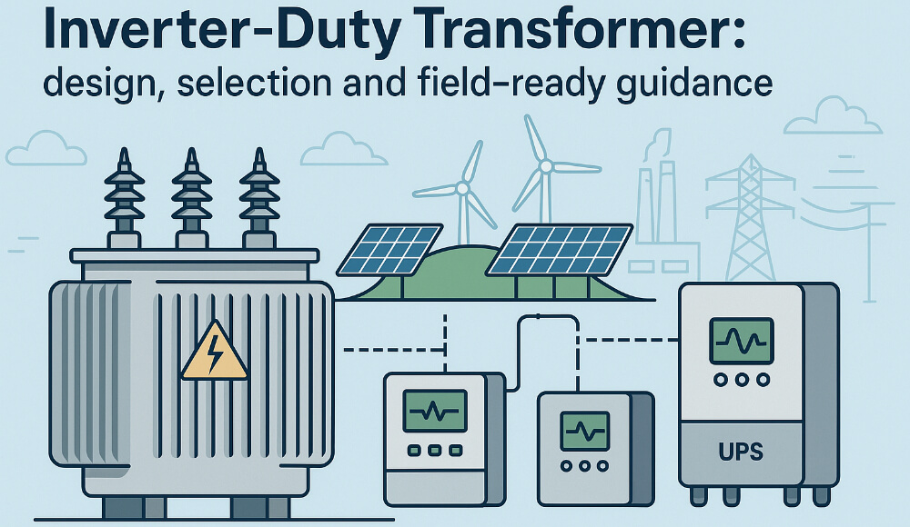
Modern grids and industrial facilities increasingly connect power-electronic converters — photovoltaic inverters, battery inverters, UPS and large VFD banks — that produce voltage and current waveforms far from the smooth sinewaves traditional transformers were designed for. An inverter-duty transformer is a purpose-built transformer that accepts those electrical realities without premature aging, overheating, or nuisance protection trips. This article explains what makes these transformers different, how to pick the right one, practical installation tips, and a commissioning & maintenance plan that keeps your asset healthy for decades.
What an inverter-duty transformer must do
At its core the device must safely transfer power between the inverter side and the grid (or distribution bus) while handling fast voltage transitions, high harmonic currents and non-sinusoidal neutral currents. Instead of fighting the inverter, it manages and mitigates the additional stresses the inverter introduces.

Key technical features that matter
Harmonic-aware thermal design: Inverters inject harmonic currents that raise localized heating in windings and structural parts. Good designs either specify a K-factor (an empirical multiplier representing harmonic heating) or provide thermal headroom so hotspots remain within insulation limits over time.
Electrostatic (capacitive) shielding between windings: A conductive shield placed between primary and secondary windings blocks the path for high-frequency common-mode currents. This reduces stress on inverter filters and reduces EMI coupling into the secondary system.
Low-loss core and tight laminations: Harmonics excite stray flux paths; better steel grades and thinner, tighter lamination stacks reduce eddy-current and stray losses at harmonic frequencies.
Neutral configuration options: Triplen harmonics (3rd, 9th, etc.) can create large neutral currents. Transformer designs that allow floating neutrals, isolated neutrals, or specially phased secondaries help manage these flows without creating unwanted ground currents.
Connection variety for harmonic control: Delta, zig-zag, and multi-winding arrangements can trap or redirect certain harmonic orders, limiting their propagation to the wider system.
Robust insulation and surge coordination: Transient dv/dt and switching spikes are common. Insulation systems, surge protection coordination and arrester mounting provisions should be specified accordingly.
Common physical forms and when to use them
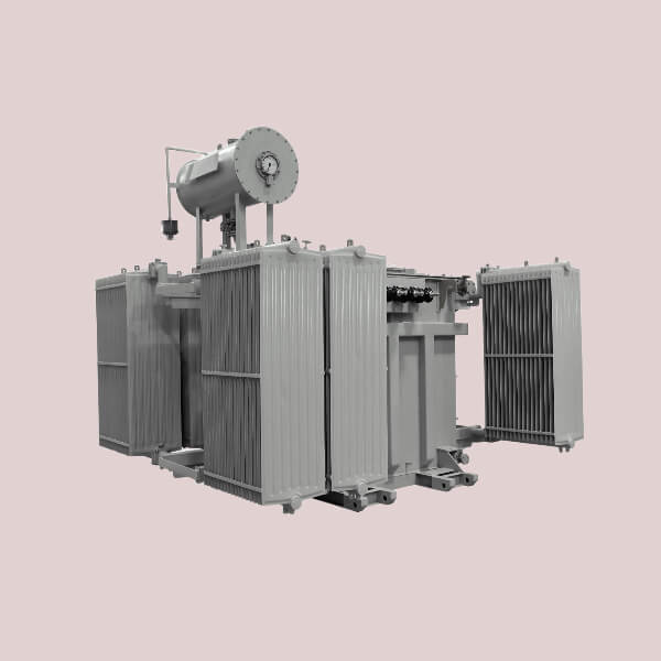
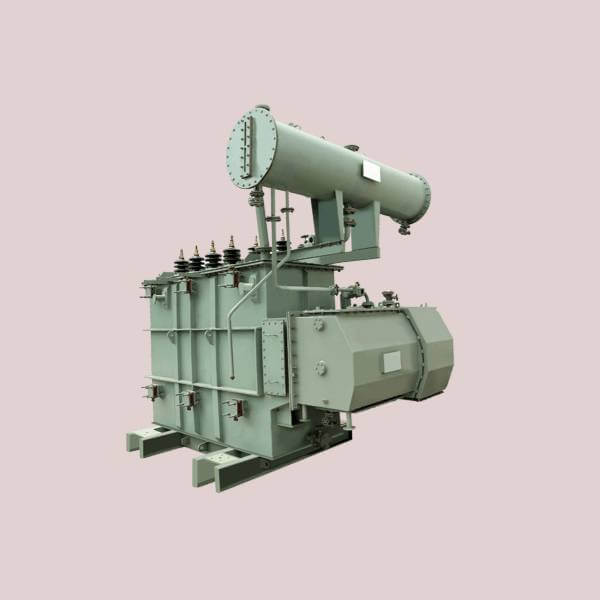
Pad-mounted oil-filled step-up — ideal for utility-scale PV farms where space, cost, and high kVA favor oil cooling and outdoor mounting.
Dry-type (cast resin or ventilated) indoor/outdoor — safer for enclosed inverter rooms, rooftops or containerized energy storage where oil is undesirable or prohibited.
Skid or container-mounted assemblies — full turn-key combos where transformer, LV switchgear and inverter sit together; minimizes field wiring but requires careful thermal and acoustic design.
How to choose the right inverter-duty transformer
Obtain the inverter harmonic spectrum. Ask the inverter OEM for measured harmonic current distribution under expected operating modes — continuous, charge/discharge, and islanding tests.
Specify duty cycle and ambient conditions. How often will the system cycle? What ambient temps, altitude and enclosure constraints apply? These affect thermal sizing.
Decide neutral behavior and grounding strategy. Floating neutral? Grounded through reactance? This impacts the transformer vector group and protective relaying.
Choose shielding and connection topology. For PV/BESS, require an electrostatic interwinding shield unless a system-level design explicitly prefers otherwise.
Ask for a harmonic heating report. Request vendor calculations showing hot-spot temperatures under the provided harmonic spectrum. If unavailable, insist on a conservative K-factor or derating.
Confirm surge protection coordination and BIL. Inverter switching may produce fast transients; verify arrester specs and insulation withstand levels.
Specify monitoring and accessories. Include winding and ambient temperature sensors, oil sampling ports (if oil), and provisions for periodic thermography.
Commissioning and initial testing highlights
Perform an energisation study to assess inrush and transient interactions with the inverter controls.
Measure vibration and noise at no-load and full-load; high vibration can indicate harmonic excitation and should be investigated.
Run an initial thermal ramp with representative inverter modes (not only steady-state) and validate hot-spot temperatures with sensors or scan thermography.
Verify harmonic currents under normal operation and compare to specification; if harmonics exceed assumptions, reduce load or adjust filtering before final acceptance.
Maintenance & long-term care
Quarterly visual and thermal checks: Look for loose connections, oil leaks, abnormal noise; use an infrared scan while the system is operating.
Annual electrical tests: Insulation resistance, power factor, and winding resistance checks to spot trends.
Oil testing (if applicable): BDV, dissolved gas analysis and moisture content per a defined schedule and after events.
Firmware/process review for inverters: As inverter control firmware updates can change harmonic profiles, re-validate transformer heating after major inverter software upgrades.
Short sample spec
“Transformer, three-phase, 2500 kVA, dry-type; LV: 690 V inverter side; HV: 33 kV grid side; vector group Yn/d-11; electrostatic interwinding shield included; thermal design qualified for K-factor 4 (or derated 15% at specified harmonic spectrum); temperature sensors in all windings; conforming to IEC 60076 and IEEE C57.x guidance for distributed generation applications.”

FAQ
Can I use a standard transformer with an inverter? Technically yes for light harmonic content, but risk accelerated aging. If harmonics are significant, a purpose-designed inverter-duty unit is strongly advised.
Do I always need an electrostatic shield? For most PV and BESS sites, yes — it’s inexpensive insurance against high-frequency common-mode stress.
Are dry transformers better for indoor inverter rooms? They avoid oil risks and are commonly preferred indoors, but ensure the dry design’s thermal margins account for harmonic heating.
An inverter-duty transformer is more than a power transfer device — it’s a reliability buffer between fast, modern power electronics and the slower, older electrical grid. Specifying the right topology, shielding and thermal design up front prevents costly surprises later and keeps both inverters and the grid operating smoothly.