Hot Keywords:
- All
- Product Name
- Product Keyword
- Product Model
- Product Summary
- Product Description
- Multi Field Search

Views: 0 Author: Welldone power Publish Time: 2026-08-20 Origin: Site


A regional grid typically employs a four-stage voltage cascade: 220 kV → 110 kV → 35 kV → 10 kV. A common question from non-specialist stakeholders is: why not step directly from 220 kV to 10 kV in one transformation and save the cost of two intermediate substations?
The answer lies in the competing physics of transmission loss and transformation economics.
Power loss in a conductor follows the relationship P_loss = I⊃2; × R. At a given power level, doubling the voltage halves the current and quarters the resistance loss. A 220 kV line carrying 200 MW over 100 km loses roughly 1.5–2% of its energy. The same power at 10 kV over the same distance would lose over 99% — the conductor would need to be impossibly large, and the voltage at the receiving end would collapse. High voltage is essential for long-distance transport.
But high voltage is expensive to distribute. A 220 kV switchgear lineup costs five to ten times more than its 10 kV equivalent per feeder bay. Insulation clearances demand larger physical footprints. Safety clearances push substations away from population centers — directly opposite to where the load actually sits. Direct 220-to-10 kV transformation at every load point would be technically possible but economically absurd: you would be installing ultra-high-voltage equipment next to every factory and apartment block.
The four-level cascade resolves this tension. Each level serves a specific function:
Voltage Level | Primary Role | Typical Substation Spacing | Typical Transformer Rating |
220 kV | Bulk transmission between regional hubs | 40–80 km | 150–300 MVA |
110 kV | Sub-transmission to city/district nodes | 10–25 km | 40–100 MVA |
35 kV | Distribution to industrial zones and rural feeders | 3–8 km | 10–31.5 MVA |
10 kV | Final distribution to consumer-level feeders | 0.5–3 km | 0.4–2.5 MVA |
The spacing column matters enormously. It is not arbitrary — it is driven by the supply radius concept, which we will examine next.
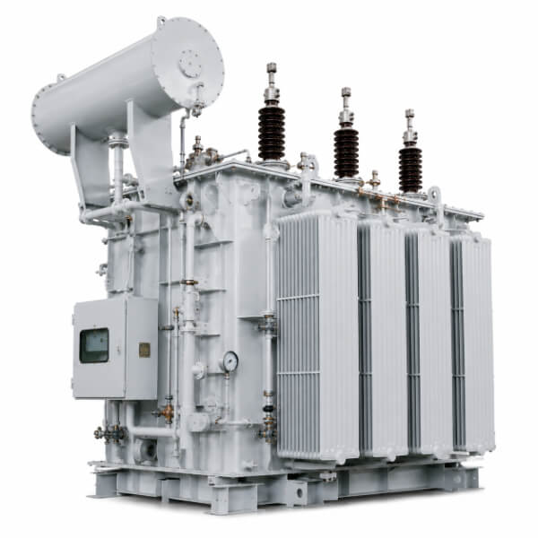
Every distribution transformer has a maximum effective supply radius — the distance beyond which voltage drop and line losses violate regulatory limits. This radius is not a number printed on a datasheet. It is a function of four interacting variables:
Secondary voltage level: Higher voltage means lower current for the same power, which means smaller voltage drop per kilometer. A 35 kV feeder can economically reach 8 km; a 10 kV feeder typically maxes out at 3 km.
Conductor cross-section: Larger conductors reduce resistance but increase cost. Grid planners select conductor sizes based on the targeted load density and acceptable loss percentage.
Load density (MVA/km²): Densely loaded urban areas can justify more substations with smaller radii; sparsely loaded rural areas force larger radii but must accept higher per-feeder losses.
Regulatory voltage tolerance: Most grid codes require voltage at the consumer point to remain within ±5% to ±10% of nominal. The feeder must be short enough that end-of-line voltage stays within this band under peak load.
Here is the connection that many specifiers miss: the supply radius determines how much load a single substation can aggregate, and that load total determines the transformer capacity.
In a residential district with a load density of 5 MVA/km², a substation with a 3 km supply radius covers an area of approximately 28 km² and aggregates a peak demand of about 140 MVA. That substation needs a transformer (or transformers) rated to handle 140 MVA with appropriate redundancy margin — which leads us directly to the N-1 criterion.
In a rural area with a load density of 0.2 MVA/km², the same 3 km radius covers the same 28 km² but only aggregates 5.6 MVA. The substation specification changes dramatically: a single 10 MVA unit is sufficient, and the entire substation design shifts from a multi-transformer indoor GIS arrangement to a single outdoor oil-immersed transformer with a simpler protection scheme.
This is why identical 110/35 kV transformers may be specified at 63 MVA for a city substation and 20 MVA for a rural one — same voltage ratio, same standard, completely different design driver. When a procurement specification simply states "110/35 kV transformer, IEC standard" without defining the load context, the manufacturer cannot optimize the design. The supply radius — and the load density it implies — is the missing variable that makes or breaks the specification.
The N-1 security criterion is the single most influential grid planning rule for transformer configuration. It states: the loss of any single component (transformer, line, busbar) shall not cause interruption of supply to any load that the grid is required to serve continuously.
For a substation with n identical transformers each rated at S_r, the N-1 criterion requires:
(n − 1) × S_r ≥ S_total
Where S_total is the total peak load of the substation's supply area. This inequality governs three decisions simultaneously:
Configuration | Normal Loading per Unit | After Loss of One Unit | Typical Application |
2 × S_r | ≤ 50% each | 100% on surviving unit | Urban distribution substations |
3 × S_r | ≤ 67% each | 100% across two survivors | High-reliability urban/transmission hubs |
4 × S_r | ≤ 75% each | 100% across three survivors | Critical transmission nodes |
With two transformers, each normally runs at only 50% of its rating — half the capital investment sits idle on any given day. With three transformers, normal loading rises to 67%, a 34% improvement in asset utilization. But adding a third transformer also adds a third winding, a third protection panel, a third bay in the switchyard, and a third set of cooling equipment. The capital cost does not scale linearly.
If a substation serves 100 MVA of peak load with two transformers, each must be rated at least 100 MVA. That is a massive unit — it approaches the transport weight limit for road delivery (typically 100–150 tonnes including oil) and may require on-site assembly for anything larger. If the same substation uses three transformers, each needs only 50 MVA. The smaller units are easier to transport, easier to replace if one fails, and easier to source from multiple manufacturers.
A transformer rated 63 MVA under ONAN (natural air cooling) can deliver approximately 75 MVA under ONAF (forced air cooling) and up to 80 MVA under ODAF (forced-directed oil and air cooling). When the N-1 criterion requires the surviving transformer to carry 100% of the load — temporarily, until the failed unit is repaired or replaced — grid planners often specify a cooling class that provides emergency overload headroom. The transformer is ordered as a 63/75/80 MVA unit (ONAN/ONAF/ODAF). The nameplate rating is 63 MVA, but the cooling fans and oil pumps give it a 27% emergency reserve.
This is a design decision that flows directly from grid architecture to the transformer's cooling system specification. It affects the cost of the transformer, its noise level in normal operation (fans off vs. running), and its long-term insulation aging profile. Specifying ONAF when the grid plan only requires ONAN is wasteful. Specifying ONAN when the N-1 analysis demands ONAF is dangerous — the surviving transformer will overheat and trip, converting a single-component failure into a cascading outage.
Substation siting aims for the load center — the geographic point that minimizes the aggregate distance (and therefore the aggregate feeder loss) to all served loads. But load centers are not stationary. Industrial parks are built, residential districts expand, and commercial corridors shift. A substation positioned at the 2025 load center may be 2 km from the 2035 load center.
This has direct consequences for transformer specification:
Tap range: A wider on-load tap-changer range (e.g., ±10% instead of ±5%) gives the transformer more room to compensate for voltage drift caused by feeder length growth. When the substation is no longer at the load center, the feeders to the new load center are longer, the voltage drop is larger, and the tap changer must work harder. A transformer ordered with a narrow tap range may run out of regulation headroom before it reaches mid-life.
Impedance percentage: When a substation serves nearby loads, lower impedance (e.g., 10%) is preferable — it minimizes voltage regulation and losses. When the same substation must serve loads at greater distances because the load center migrated, higher impedance (e.g., 12–14%) helps limit short-circuit current at the end of longer feeders where protective devices may have lower interrupting ratings. The impedance value is frozen at the design stage; you cannot change it after the transformer is built.
Future expansion capacity: A substation initially equipped with two transformers should be designed to accommodate a third. This means the civil foundation, oil containment pit, and fire separation distances must be pre-planned. The transformer manufacturer needs to know this at the design stage — the oil containment system, for instance, must be sized for the largest possible future unit, not just the initial one.
When ordering a power transformer for a substation whose load center is expected to migrate over its 30-year service life, the specification should include:
Load forecast data: Provide the 10-year and 20-year projected load profiles, not just the current peak demand. The manufacturer needs this to size the cooling system and estimate the insulation aging rate under the expected loading profile.
Supply radius and feeder length data: State the maximum and average feeder lengths at the time of commissioning and the projected maximum in 10 years. This helps the manufacturer select the appropriate tap-changer range.
System short-circuit capacity: Provide the maximum and minimum short-circuit levels at the transformer's primary and secondary terminals, both now and projected. This determines the optimal impedance percentage — too low, and the secondary short-circuit current exceeds the breaker ratings; too high, and the voltage regulation suffers.
N-1 contingency requirement: Explicitly state whether the transformer must carry 100% of the substation load if one unit is lost, and for how long. This determines whether forced cooling is needed and at what capacity.
To make the grid-to-transformer connection concrete, here is how each level in the step-down chain maps to specific transformer design parameters that manufacturers must optimize:
Grid Architecture Decision | Transformer Parameter Affected | Design Consequence |
Number of voltage levels | Transformer voltage ratio (e.g., 220/110 kV) | Determines winding insulation grading and tap-changer voltage class |
Supply radius at each level | Rated capacity (MVA) | Determines core and winding dimensions, transport weight, cooling class |
N-1 requirement at each substation | Number of units + cooling class | Determines whether ONAN suffices or ONAF/ODAF is needed for emergency overload |
Load center stability over 20+ years | Tap-changer range and type (OLTC vs. NLTC) | OLTC with ±10% range costs more but provides long-term flexibility; NLTC with ±5% is cheaper but rigid |
Feeder length growth projection | Impedance percentage (%Z) | Higher %Z limits short-circuit current growth; lower %Z improves voltage regulation |
Load density and load factor | No-load loss vs. load loss ratio | High-load-factor substations benefit from low load loss; low-load-factor substations benefit from low no-load loss (amorphous core) |
The last row deserves emphasis. A 220/110 kV transformer in a transmission hub runs at high loading 24 hours a day — load losses dominate total energy loss, and the manufacturer should optimize the winding design for low copper loss. A 35/10 kV transformer in a residential area runs at 20% load at night and 80% during evening peak — no-load losses (core losses) run continuously and may exceed load losses over a 24-hour cycle. For this unit, the manufacturer should optimize for low no-load loss, which may mean a different core material (grain-oriented silicon steel vs. amorphous alloy) and a different core geometry.
Both transformers may carry the "IEC standard" label, but they are fundamentally different machines — optimized for fundamentally different grid positions. A procurement specification that does not communicate this context forces the manufacturer to design for the average, which is suboptimal for every specific application.
Consider two substations that Welldone has supplied transformers for, both operating at 110/35/10 kV, both nominally "power transformers" — but with radically different specifications driven by their grid positions.
Substation A — Urban Industrial Zone
Load density: 8 MVA/km², supply radius: 1.5 km
Peak load: 90 MVA, N-1 required
Configuration: 2 × 63 MVA, ONAN/ONAF (63/75 MVA)
Impedance: 12.5% (high, because the 35 kV feeders are short and short-circuit current must be limited for the available vacuum circuit breakers)
Tap changer: ±8 × 1.25% on-load (wide range, because load growth is rapid and feeder lengths are changing)
Cooling: ONAF fans sized for continuous operation, because N-1 analysis shows the surviving transformer may carry 90 MVA for several hours before load can be transferred to neighboring substations
Noise: specified at ≤75 dB(A) at 1 m with fans on, because the substation is 200 m from a residential boundary
Substation B — Rural Agricultural District
Load density: 0.15 MVA/km², supply radius: 8 km
Peak load: 12 MVA, N-1 not required (single transformer, mobile spare unit available within 48 hours)
Configuration: 1 × 16 MVA, ONAN only
Impedance: 10% (lower, because the 35 kV feeders are long and voltage regulation is the binding constraint — the lower impedance helps maintain end-of-line voltage)
Tap changer: ±2 × 2.5% off-load (narrow range, because load growth is slow and the grid is stable)
Cooling: ONAN only — no N-1 requirement, no need for emergency overload headroom
Noise: no special requirement, substation is in an open field with no neighbors within 500 m
These are both 110 kV transformers. They could not be more different. If Substation A's specification were accidentally applied to Substation B, the rural utility would pay for ONAF cooling, OLTC, and oversized capacity it will never use — a 40-60% cost premium with zero benefit. If Substation B's specification were applied to Substation A, the urban substation would fail its N-1 test on day one, and the tap changer would run out of range within five years as industrial load grew.
Before issuing a tender for a power transformer in a regional grid, the following questions should be answered and communicated to the manufacturer. Each one directly shapes the transformer design:
What is the planned and projected load at this substation for the next 10 and 20 years? This determines the rated capacity and whether staged expansion (add a second unit later) should be anticipated.
What is the N-1 requirement? Is it full N-1 (surviving transformer carries 100% indefinitely), or is partial load transfer to neighboring substations permitted (e.g., 70% self-supply + 30% transfer)? The answer determines the cooling class and whether the substation needs two units or one unit with a mobile spare.
What is the system short-circuit level at the primary and secondary terminals, now and projected? This determines the optimal impedance. If the grid is growing and short-circuit levels are rising, a slightly higher impedance may be chosen to give the switchgear room to breathe.
What are the maximum and average feeder lengths, and how are they expected to change? This determines the tap-changer range. If feeder lengths are growing, specify a wider OLTC range now — retrofitting a different tap changer is practically impossible after manufacturing.
What is the load factor (ratio of average load to peak load)? This determines the no-load-loss-to-load-loss optimization ratio. A high load factor favors low load loss (more copper); a low load factor favors low no-load loss (better core material or amorphous alloy).
Power transformer configuration in regional grids is not a catalog selection exercise. It is an engineering translation process — converting the grid planner's architecture decisions (voltage levels, supply radii, N-1 criteria, load forecasts) into the manufacturer's design parameters (capacity, impedance, tap range, cooling class, loss optimization). When this translation is done explicitly and communicated through the procurement specification, the result is a transformer that fits its grid position like a key in a lock. When it is done implicitly — or not at all — the result is a transformer that sort of works, costs more to operate than it should, and will not accommodate the load growth that the grid planner already knew was coming.


