Hot Keywords:
- All
- Product Name
- Product Keyword
- Product Model
- Product Summary
- Product Description
- Multi Field Search

Views: 0 Author: Welldone power Publish Time: 2026-08-11 Origin: Site


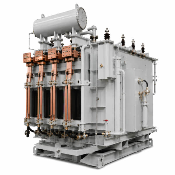
An arc furnace transformer does far more than step down grid voltage. It operates at the heart of a steel melt shop, converting high‑voltage input into a torrent of low‑voltage, high‑current output that can exceed 100 kA at the secondary side. Yet its true engineering significance lies not in its rated power, but in its ability to survive relentless electrical, mechanical, and thermal abuse—electrode jamming, scrap collapse, arc instability, and repeated short‑circuit events that would destroy ordinary power transformers within weeks. This article dissects the critical design layers that define a robust furnace transformer, from impedance tuning and winding mechanics to cooling strategies and terminal engineering.
The per‑unit impedance (Uk%) is often listed as a static figure, but in practice it functions as the transformer’s primary defence against fault currents. Lower impedance yields a higher secondary voltage under load, accelerating the melt‑down phase—but it also reduces loop resistance, allowing short‑circuit currents to reach 20 to 25 times the rated value during electrode immersion. To strike a balance, most large EAF transformers are deliberately designed with higher impedance, typically between 14% and 18%, without sacrificing no‑load voltage performance. This is frequently achieved by integrating a series reactor—either inside the main tank or as a separate external unit—which adds leakage reactance while decoupling the main windings from the worst mechanical shocks.
Impedance, however, is not uniform across the transformer. The longitudinal leakage field, which runs parallel to the winding axis, dictates the axial force distribution during a fault. Finite‑element simulations consistently show that axial forces peak near the winding ends, where magnetic field lines fringe outward. Consequently, end‑ring clamping pressure—measured in tons per square metre—proves more critical than radial bracing alone. A transformer that passes a symmetrical short‑circuit test may still fail in service if axial pre‑compression relaxes after thermal cycling, a risk that can be mitigated through constant‑pressure drying and mechanical locking systems.
The secondary winding, typically foil‑wound or spiral‑wound with multiple parallel conductors, experiences radial forces that attempt to expand it like a pressure vessel. Copper foil offers excellent short‑time thermal capacity, but its mechanical modulus is lower than that of transposed cable. For currents above 50 kA, designers often combine continuously transposed cable (CTC) for inner layers with heavy rectangular copper for outer layers, each selected for specific stress orientations. A crucial but often overlooked detail is the interleaved paper insulation between disc packs—it not only provides dielectric strength but also acts as a friction damper, dissipating vibrational energy through hysteresis rather than transmitting it to terminal connections.
Axial clamping deserves equal attention. During a short circuit, the inner winding tends to shorten axially under radial field compression, while the outer winding attempts to elongate. This differential movement, if unchecked, shears turn‑to‑turn insulation and pulverises end blocks. Modern designs apply a pre‑stress of 4–6 MPa to the entire winding stack, locking it with through‑bolts or hydraulic nuts. Yet pressure alone is insufficient; elastic recovery of copper and paper after heat cycling must be accommodated by Belleville washers or spring‑loaded end rings, ensuring that clamping force remains stable over decades of operation.
Furnace operators demand voltage steps fine enough to prevent arc extinction during refining, yet coarse enough to speed up melt‑down. The on‑load tap‑changer (OLTC) selection must reconcile these conflicting needs with insulation coordination of the main winding. Coarse‑fine (or plus‑minus) regulation is preferred for large EAF units because it reduces the number of tap positions on the high‑voltage side, allowing the regulating winding to share only a fraction of the total insulation level. However, this topology introduces a transition impedance that must be carefully rated—if the bridging resistor fails, the diverter contacts face repetitive make‑break currents beyond their duty.
The step voltage—the difference between adjacent taps—is another subtle parameter. Too large a step forces the arc current to jump dramatically, triggering protective trips; too fine a step wastes contact life and complicates control logic. In practice, the optimal step voltage falls between 2.5% and 4% of the rated primary voltage per tap, verified by thermal imaging of the diverter switch during factory type tests. Many field failures of OLTCs trace back not to contact undersizing, but to a mismatch between the transition resistor’s time constant and the motor drive’s switching speed.
Cooling is never a standalone calculation; it is tightly coupled with the overload capability that steel mills routinely expect. While ONAN (oil natural, air natural) suffices for small ladle furnaces, most EAF transformers operate under ONAF (oil natural, air forced) or OFWF (oil forced, water forced). Simply increasing fan power does not linearly improve rating—oil flow distribution inside the tank must be analysed. Stagnant zones often develop between the core and the inner winding, where oil velocity drops below 0.3 m/s, causing hot‑spot temperatures that exceed the winding average by 15–20 K. Thermal models must map these zones and adjust duct spacing—wider near the top, narrower near the bottom—to promote natural convection even under forced flow.
OFWF systems introduce additional complexity: the oil‑water heat exchanger’s fouling factor. In mills with poor water quality, scale formation on the water side raises the terminal temperature difference, forcing the oil pump to work harder and risking cavitation. A comprehensive design includes not only cooler capacity but also recommended cleaning intervals and pressure‑drop alarms linked to oil viscosity. The real thermal limit, however, is not the top‑oil temperature but the winding hot‑spot gradient, which can only be accurately measured via embedded fibre‑optic sensors during a heat‑run test—an 8‑ to 12‑hour procedure that ultimately validates the cooling system’s ability to sustain 150% overload for 30‑minute bursts, a duty cycle seldom written into contracts but invariably expected.
Conducting 80 kA through a tank wall without melting the surrounding steel is a metallurgical challenge as much as an electrical one. Secondary bushings must incorporate two parallel paths: one for current (through copper or aluminium tubes) and one for cooling fluid (deionised water circulating inside the conductor). The wall penetration creates a concentrated magnetic flux that induces eddy currents in the tank flange, often exceeding 200°C locally. Standard countermeasures—using non‑magnetic stainless steel or cutting radial slots in the flange—must be validated by 3D transient magnetic simulation, as slot geometry alters the field distribution and can create new hot spots at slot tips.
Internal lead connections from the secondary winding to bushing studs represent hidden failure points. Since these leads are not immersed in the main oil flow, they rely on conduction and radiation for cooling. Multi‑layered laminated copper strips with pre‑formed insulation spacers are commonly employed, ensuring equal current sharing among layers. Joint resistance at crimped or brazed interfaces must remain below 2 micro‑ohms; otherwise, ohmic loss at that spot exceeds 15 kW, sufficient to carbonise adjacent pressboard within a year. DC resistance measurement of each lead assembly before final assembly, with a tolerance of ±3%, is therefore a mandatory quality check.
Routine tests—ratio, resistance, no‑load loss—are merely the prelude to type tests that define a transformer’s pedigree. The short‑circuit withstand test, performed at the first principal tap and the most unfavourable tap, subjects the unit to three symmetrical faults, each lasting 0.5 seconds, with the first peak reaching 2.55 times the RMS symmetrical current. Passing this test does not guarantee field survival, because the test is conducted at ambient temperature with fresh oil, whereas in service the transformer is hot, oil has aged, and clamping pressure may have relaxed. Many reputable designs therefore incorporate a margin of 120% of the test current, and post‑test measurement of leakage reactance—a change of more than 0.5% indicates dimensional winding shift—provides a valuable early warning.
The lightning impulse test with chopped wave is another discriminator. While the full‑wave test verifies main insulation, the chopped‑wave test, with its steep‑fronted voltage collapse, stresses inter‑turn insulation—especially in the first few discs of the line‑end winding. The choice of enamel insulation, such as double‑ply glass‑fibre with epoxy overcoat, must be correlated with breakdown voltage measured from sample coils, not just supplier datasheets.
A furnace transformer is rarely a customer’s first; its performance in hot‑spot temperature, tap‑change reliability, and oil degradation will be compared against previous units from competing suppliers. The hidden differentiator is often the copper‑to‑iron ratio—the deliberate addition of extra copper to lower current density and reduce cyclic thermal stress. This increases upfront cost but extends insulation life by a factor of two for every 10 K reduction in hottest‑spot temperature. Sound engineering practice follows IEC 60076‑7 for ageing acceleration, targeting a normal life of 30 years at 120% load for 5% of operating time—a realistic, not optimistic, scenario.
In essence, the furnace transformer is a marriage of electromagnetics, material science, and precision craftsmanship. Its performance depends on the tension of clamping bolts, the purity of insulating oil, and the timing accuracy of the tap‑changer—details that ultimately convince a seasoned melt‑shop manager to trust that iron core with their production schedule. This holistic understanding of design, testing, and operational demands is what separates a reliable power asset from a recurring maintenance liability.


