Hot Keywords:
- All
- Product Name
- Product Keyword
- Product Model
- Product Summary
- Product Description
- Multi Field Search

Views: 0 Author: Welldone power Publish Time: 2026-09-17 Origin: Site


Every utility-scale solar farm and battery storage site has one enclosure that never appears in the marketing renders: the box-type substation sitting between the inverter containers and the grid connection point. It is not the largest piece of equipment on site, and it is rarely the most expensive. Yet it is the component through which every kilowatt-hour generated, stored, and sold must pass — twice, in the case of storage, because energy flows both in and out.
Visit enough renewable sites and you will notice that these substations are not built to a single template. Two architectures dominate. One descends from the American pad-mounted tradition: a sealed, oil-immersed compartmental cabinet, compact and largely self-effacing, with the transformer at its core. The other descends from the European prefabricated tradition: a modular walk-in style enclosure built around medium-voltage switchgear, often paired with a dry-type transformer, and designed to be extended and reconfigured. Manufacturers now build dedicated "new energy" versions of both, tuned for the peculiar demands of photovoltaic and battery installations.
The interesting part is not which one is "better." It is that both architectures must answer the same five engineering questions — and they answer them differently because they inherited different philosophies. Understanding those questions, and the trade-offs behind each answer, is what separates a substation that quietly serves a plant for twenty-five years from one that trips its way through the first summer.
A conventional distribution substation was designed around a predictable story: power flows from the grid, through the transformer, to the load. The load follows human rhythms — heavy in the morning and evening, lighter at night. Fault current comes from the network side. Nobody touches the equipment most days.
Power flows both directions: a battery enclosure charges from the grid at night and discharges into it during the evening peak, which means the low-voltage side occasionally behaves like a source rather than a load. The current itself is not clean — power conversion systems chop DC into AC with switching semiconductors, injecting harmonic currents and a small but troublesome DC component into the transformer's low-voltage winding. The load profile is violent rather than gentle: a cloud edge can take a photovoltaic feeder from full output to near zero in seconds, and a frequency-regulation battery can swing from full charge to full discharge within a single duty cycle, several times an hour. And the site itself is often remote and unmanned, fenced behind a solar field or on a plateau accessible only by one road.
None of these conditions appears in the design assumptions of a standard compact substation built for a residential estate or a commercial block. The two architectures we are about to compare exist precisely because those assumptions had to be rebuilt from scratch.
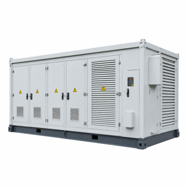
The transformer at a solar or storage site does not see the sinewave world of a utility network on its low-voltage side. It sees the output of power electronics.
Three electrical problems follow, and each architecture addresses them at the winding design stage rather than with bolt-on fixes.
Harmonic heating. Harmonic currents from the conversion equipment increase winding eddy losses and stray losses in the tank and core, and their heating concentrates in places that a standard loss test never measures. Transformer windings for new-energy duty are therefore designed with enlarged conductor cross-sections and strand transpositions chosen specifically to keep AC resistance — not just DC resistance — low across the harmonic spectrum. In the pad-mounted architecture, the delta-connected winding facing the inverter does double duty: it traps triplen harmonics in a circulating loop, keeping them out of the grid.
DC bias. Inverters leak a small direct-current component into the low-voltage terminals. A few amperes of DC are enough to push the core into one-sided saturation, which shows up as excitation current spikes, audible hum, vibration, and localized heating. The countermeasure is deliberately conservative: designers run the core at a reduced flux density, buying a wide margin between normal operation and saturation. It costs a little more steel. It prevents a family of field failures that are miserable to diagnose remotely.
Dual-winding integration. Here the two architectures reveal a genuine design divergence. The pad-mounted new-energy substation commonly integrates a double low-voltage winding — for example, one winding rated for the 10 kV-class grid and a second at 690 V or 350 V dedicated to the storage conversion equipment — inside a single tank. One enclosure, one oil system, one foundation, serving both the photovoltaic feeder and the battery feeder. The European-style approach more often keeps functions in separate modules within the enclosure: switchgear bay, transformer bay, low-voltage bay — and where conversion integration is deep, pairs the enclosure with a purpose-built dry-type unit. The single-tank solution minimizes interfaces and footprint; the modular solution maximizes serviceability and fire segregation. Neither is wrong. They optimize different definitions of "risk."
A transformer converts a few percent of everything that passes through it into heat. In an open substation yard, that heat simply leaves. In a box — especially a fully sealed, tamper-resistant, weatherproof box — heat rejection becomes a design problem in its own right, and it interacts badly with everything else the enclosure must do.
Sealing protects the internal equipment from dust, salt fog, and intrusion, but sealing also insulates. The pad-mounted architecture resolves this paradox with an elegant piece of passive engineering: the heat pipe. A heat-pipe assembly attached to the tank wall moves heat outward through the enclosure skin and dissipates it via external fins, with no fans, no pumps, no filters, and no openings through which dust or fingers can enter. Combined with a fully welded, hermetically sealed tank that never breathes air or moisture, the design suits unmanned sites in coastal, desert, or high-humidity environments — precisely where most utility-scale renewable plants are built. Passive cooling also has a maintenance story that unmanned sites love: there is nothing to service.
The European-style enclosure takes the opposite trade. It accepts that a walk-in modular station will have ventilation paths, and manages them: filtered louvers, forced-air circulation for the dry-type transformer bay, and temperature monitoring distributed through the compartments. Forced air moves more heat and allows higher power density in the same footprint, but it introduces moving parts and filters into an environment that may see a service visit twice a year. The honest comparison is this: the sealed passive design bets that nothing inside will ever need attention; the ventilated modular design bets that things inside will need attention, and makes that attention easy. A twenty-five-year life-cycle calculation on an unmanned site tends to favor the first bet; a site with resident technicians tips toward the second.
Renewable plants are rarely built once. A photovoltaic site expands in phases as land and capital allow; a storage plant adds battery containers as market rules and revenue streams evolve. Every expansion lands on the substation as a request for more capacity, more feeders, more switchgear positions.
This is where the European-style architecture shows its ancestry. The modular enclosure is designed with expansion in the hardware itself: bolt-on busbar extensions at the top or side of the enclosure, standardized switchgear panels, and provisions for paralleling multiple stations so that a second unit can be added and ganged with the first without redesigning the medium-voltage bus. Capacity growth becomes a crane lift and a cable-pulling exercise rather than a civil works project. For phased projects with uncertain future scope, this modularity is not a luxury — it is the difference between a five-day expansion and a five-week outage.
The pad-mounted architecture answers the same need differently: by keeping each unit small, standardized, and replicable. Instead of growing one enclosure, the site deploys more of them. The single-tank dual-winding design supports this too — several units can serve different generation blocks, each factory-tested as a complete system before it ships. The trade-off is busbar complexity on site: paralleling sealed units happens in the field, in cable trenches and junction boxes, not in a factory. Project developers effectively choose between buying flexibility from the factory (modular enclosures) or buying simplicity from the factory and accepting field integration work.
A renewable site may see a technician twice a month. Everyone else who approaches the enclosure — a farmer, a trespasser, a first responder — is untrained in what is inside. Safety design must therefore work without supervision, which pushes both architectures toward engineered interlocks rather than procedures.
The European-style station concentrates its safety effort in mechanical interlocking of the switching sequence: the enclosure's operating mechanisms are coupled so that an operator physically cannot open a medium-voltage compartment under load, cannot withdraw a breaker to an incorrect position, and cannot close into an earthed circuit. The interlocks are in the hardware, not the checklist. Around them sit arc-monitoring systems that detect an internal fault's light and pressure signature within milliseconds and trip upstream protection before the arc can breach the compartment, plus real-time condition monitoring — transformer temperatures, switchgear status, door positions — streamed to a remote control room.
The pad-mounted station, having no walk-in space, takes a different route: complete compartmental separation. The high-voltage compartment, the transformer compartment, and the low-voltage compartment each have independent lockable doors; an unauthorized opening of one compartment exposes no live parts of another. Its oil-immersed, sealed construction removes the combustible-gas and arc-flash exposure that open switchgear carries, and its monitoring package — oil temperature, winding temperature, remote status signaling — is built for integration with the plant's supervisory control system. Fire behavior also diverges: mineral-oil units rely on sealed-tank design and site layout clearances, while the European modular station offers a dry-type transformer option that eliminates insulating liquid entirely — increasingly the preferred answer where the enclosure sits close to battery containers or buildings, because the fire-load conversation with insurers and permitting authorities gets materially easier.
After five questions and two sets of answers, the selection logic compresses into a handful of decisions:
Remote, unmanned, harsh environment, minimal maintenance budget → the sealed pad-mounted design wins on passive cooling, zero-breathing tank construction, and the absence of anything requiring scheduled attention.
Phased expansion, frequent reconfiguration, co-located with battery containers or occupied buildings → the modular European-style design wins on busbar extension, dry-type fire segregation, and interlock-rich operability.
Integrated storage duty → the dual-winding single-tank solution minimizes interfaces between photovoltaic, storage, and grid feeders; the modular solution preserves independence between them.
Insurer and permitting pressure on fire load → dry-type within the modular enclosure, or generous separation distances for oil units.
The deeper point is that the question "which box-type substation should we buy" is really five smaller questions, and every vendor's datasheet implies answers to all of them — whether the designer thought about them or not. A substation that is merely a standard product with "new energy" on the nameplate will answer the bidirectional-duty question with a shrug, and the first year of operation will collect the evidence: nuisance trips on harmonics, oil temperatures that never quite recover overnight, expansion plans that die in quotation stage.
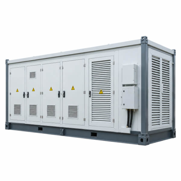
A procurement specification for a new-energy box-type substation should therefore ask for evidence, not adjectives:
Winding design documentation for harmonic and DC-bias duty — eddy-loss calculations across the harmonic spectrum, and the design flux density, not just the standard test report.
A thermal verification against the site's actual duty cycle — charge-discharge cycling profiles, not a continuous-rated loading assumption.
Cooling-system maintenance scope over 25 years — fans, filters, and service visits for ventilated designs; zero scheduled service for sealed passive designs.
Expansion provisions in writing — busbar extension interfaces, paralleling capability, and what a capacity upgrade physically involves.
Interlock and arc-fault documentation — the switching-sequence interlock logic, arc detection response time, and remote monitoring point list.
Fire-risk file — fluid type and fire point for oil units, or the dry-type certification path, together with site layout clearances.
Six lines of evidence do more to separate genuine new-energy designs from relabeled stock products than any amount of brochure vocabulary.
The box-type substation at a solar or storage plant is where two electrical worlds — the switched, harmonic-rich, bidirectional world of power electronics and the steady, directional world of the grid — are made to coexist inside one painted steel enclosure. American-style and European-style architectures get there by different roads: one by sealing the problem out, the other by modularizing the problem apart. What matters for a project is not the label but the answers to the five questions above, asked early, answered with evidence, and written into the specification before the purchase order — because after commissioning, the enclosure will quietly enforce whatever engineering went into it, in both directions, every single day.


