Hot Keywords:
- All
- Product Name
- Product Keyword
- Product Model
- Product Summary
- Product Description
- Multi Field Search

Views: 0 Author: Welldone power Publish Time: 2026-09-30 Origin: Site


A converter transformer is the only component in an HVDC link that stands between the alternating-current grid and the converter valves. It is not a power transformer with a different name: it must survive combined AC and DC voltage stress, valve-side DC premagnetization, and harmonic heating that a standard unit is never designed for.
That distinction is the whole point of this article. Most explanations of converter transformers describe what they do — step voltage, shift phase, isolate. Fewer explain why a unit built to the power-transformer rulebook quietly fails in an HVDC station. The three special stresses below are not features to advertise; they are failure modes a buyer's specification must explicitly budget for, or the station pays for them later in the field.
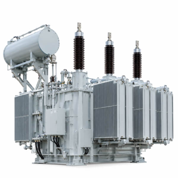
An HVDC link has two ends. At the sending end a converter station acts as a rectifier, turning AC into DC; at the receiving end a second station acts as an inverter, turning it back. A converter transformer sits at each end, directly between the AC busbar and the valve bridge — the stack of thyristors or IGBTs that actually performs the conversion.
Three functions fall to this one machine that a normal power transformer never performs:
Galvanic isolation between the AC system and the DC potential, so direct voltage cannot walk back into the grid.
Phase shifting — the converter is built as a pair, one winding connected star (wye) and the other delta, giving a 30-degree shift that lets the two halves form a 12-pulse bridge and cancel the lowest harmonics.
Voltage transformation matched to the valve, not to a fixed grid tap.
A conventional power transformer sees a clean alternating waveform its entire life. A converter transformer sees alternating voltage, a standing DC potential from the valve, and a rich harmonic spectrum — all at once, on the same winding. That single sentence explains every special requirement that follows.
On the valve side, the winding is not stressed by AC alone. It carries the superposition of the operating AC voltage, the DC potential imposed by the converter, and the harmonic content of the converted current. The insulation must hold under a mixed field that has no equivalent in an AC-only design.
The practical consequence shows up in testing. A converter transformer is qualified with a combined AC and DC withstand test plus a polarity-reversal test (covered under IEC 61378-2 for HVDC converter transformers), not merely the AC withstand and induced-voltage tests of IEC 60076 that qualify an ordinary power transformer. Polarity reversal matters because the DC polarity at the valve can reverse during operation; an insulation system validated only against a fixed polarity can break down when the bias flips.
A unit built to the higher solid-insulation ratio that this mixed stress demands carries a far larger share of solid dielectric than a comparable AC transformer. The lesson for the spec-writer: if the document only calls out the AC withstand, the valve winding is being qualified for a world it will never operate in, and the real failure is designed in before the factory door closes.
The DC potential on the valve side does not just sit on the insulation. It also biases the magnetic core — pushing the operating point off the symmetric AC loop. The result is a shifted flux density, a growing even-harmonic content in the magnetizing current, higher audible noise, extra stray losses, and in the worst case overexcitation that no AC-only design margin was sized to absorb.
This is a different failure family from overload. A standard transformer's core is designed around a symmetrical alternating flux; it has no requirement to tolerate a standing DC bias. A converter transformer's flux margin and core construction must be specified against the expected DC premagnetization, or the unit arrives efficient on paper and noisy, lossy, and marginal in service.
The specification has to state this explicitly. "Transformer, HVDC service" is not enough; the document should require verification of DC-bias tolerance and name the flux-density margin the core must retain under the valve's standing potential.
Conversion is not sinusoidal. The converter draws current rich in the 5th, 7th, 11th, and 13th harmonics and beyond. The 30-degree star/delta phase shift between the two transformer halves cancels the 5th and 7th, which is precisely why HVDC uses a 12-pulse arrangement rather than a single 6-pulse bridge. But the 11th, 13th, and higher-order components survive, and they deposit additional copper and stray losses exactly where a fundamental-only thermal model says there is headroom.
Those stray losses concentrate in winding ends, lead structures, and tank walls — the classic locations of local hot spots. A cooling system sized from the rated MVA and the fundamental load alone will under-perform against the real harmonic spectrum. The thermal design must be evaluated against the harmonic loss, not the nameplate.
For the buyer, this is a procurement trap hiding in plain sight: a transformer accepted on a fundamental-frequency temperature-rise test can still run hot under converted current. The acceptance test plan should include loss evaluation under the harmonic content the unit will actually carry.
Condition | Conventional power transformer | Converter transformer (HVDC) |
Voltage stress on valve/secondary winding | Pure AC, symmetrical | Superposed AC + standing DC + harmonics |
Core excitation | Symmetrical alternating flux | AC flux plus DC premagnetization bias |
Loss basis for cooling | Fundamental-frequency load | Fundamental plus harmonic-spectrum losses |
Phase-shift role | None (grid frequency only) | Star/delta pair enables 12-pulse operation |
Insulation proportion | Standard solid/liquid mix | Substantially higher solid-insulation share |
Qualifying tests | IEC 60076 AC withstand, induced voltage | IEC 61378-2 combined AC/DC withstand and polarity reversal |
The table is the shortest answer to "can't we just use a bigger power transformer?" — no, because the stresses a converter transformer must survive are not present in the standard unit's design basis at all.
A procurement specification for an HVDC converter transformer should demand evidence, not adjectives:
Combined stress testing — name the AC/DC withstand and polarity-reversal test per IEC 61378-2, not only the IEC 60076 AC tests.
DC-bias tolerance — require verification of core behavior under the valve's standing DC potential, with a stated retained flux-density margin.
Harmonic loss evaluation — specify that cooling and temperature-rise are validated against the expected harmonic spectrum, not the fundamental alone.
12-pulse pair and impedance matching — state the star/delta arrangement and the tight impedance tolerance across taps (IEC 61378-2 constrains impedance variation so the two halves cancel harmonics as designed).
Valve-side insulation class — define the insulation coordination including transient overvoltages from lightning and switching superimposed on the DC bias.
Factory test package — require the combined-voltage test records, polarity-reversal results, and harmonic-load temperature-rise evidence to ship with the unit, so site acceptance is confirmation, not discovery.
Six lines of evidence separate a converter transformer qualified for HVDC service from a power transformer wearing the right nameplate.
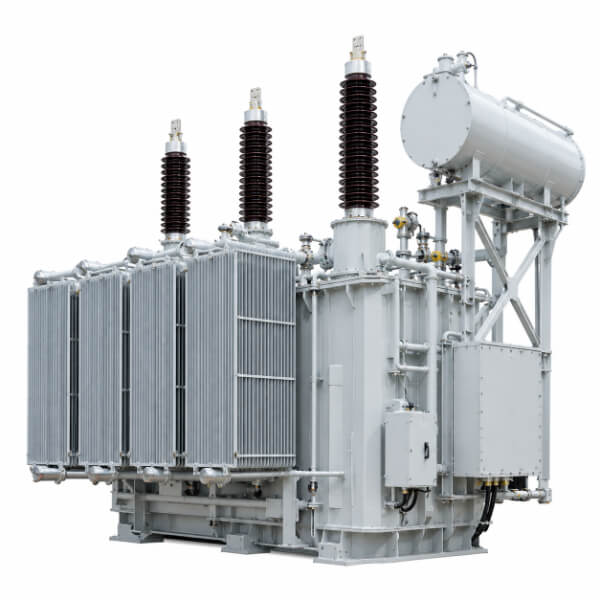
Q: What is the difference between a converter transformer and a power transformer?A: A power transformer handles a clean alternating waveform. A converter transformer bridges the AC grid and the converter valves, so its valve-side winding carries combined AC and DC voltage, a DC core bias, and harmonic current — stresses absent from the power-transformer design basis.
Q: Why does a converter transformer need a polarity-reversal test?A: The DC potential at the valve can reverse during operation. An insulation system validated only at a fixed polarity can fail when that bias flips, so IEC 61378-2 requires a polarity-reversal test that a standard AC transformer never faces.
Q: How do converter transformers reduce harmonics?A: They are built as a star/delta pair with a 30-degree phase shift, forming a 12-pulse bridge that cancels the 5th and 7th harmonics. Higher-order harmonics remain and must be handled in the thermal design.
Q: Can a standard power transformer be used inside an HVDC station?A: Not on the converter side. The mixed AC/DC stress, DC premagnetization, and harmonic heating are outside the power-transformer rulebook; only a unit qualified to IEC 61378-2 belongs between the AC bus and the valves.
Q: Which standard covers HVDC converter transformers?A: IEC 61378-2 governs converter transformers for HVDC applications, including the combined AC/DC withstand, polarity-reversal, and impedance-tolerance requirements that distinguish them from IEC 60076 power transformers.
A converter transformer is the point where the AC grid and the DC link stop being separate systems and actually meet. It earns that role only when its specification names the three stresses a power transformer never sees — combined AC/DC field, DC premagnetization, and harmonic heating — and proves them with the right tests. Specify it as a power transformer with extra ratings and the station inherits failures that were designed in at the factory. Specify it for what it truly is, and the hub that connects two grids keeps doing its quiet, irreversible job.


