Hot Keywords:
- All
- Product Name
- Product Keyword
- Product Model
- Product Summary
- Product Description
- Multi Field Search
Views: 0 Author: Site Editor Publish Time: 2025-10-31 Origin: Site


Transformers are central to power systems, and their longevity depends on choices made long before shipment: smart design, careful materials selection, disciplined manufacturing and structured after-sales support. This article walks through the full manufacturing lifecycle and highlights the engineering and process decisions that produce transformers built to last.

Durability begins at spec stage. Collect real operating data (ambient range, load profiles, harmonics, altitude, fault culture) and convert those into measurable requirements: rated kV/kVA, cooling class, short-circuit withstand, insulation class, and expected harmonic content.
A conservative thermal margin — sizing conductors and cooling for lower hot-spot temperature under realistic overload cycles — lengthens insulation life. Explicitly require moisture, corrosion and seismic considerations where relevant.
Not all steels, copper or oils are equal.
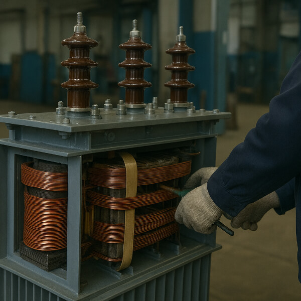
Core steel: Grain-oriented silicon steel with tight thickness control reduces losses and mechanical noise. Lamination quality and coating consistency matter for long-term stability.
Windings: High-conductivity copper is preferred for thermal margin and cyclic fatigue resistance; aluminum can be used cost-consciously but needs special joints and larger cross sections.
Insulation: Select paper, pressboard and modern insulating composites rated for the expected thermal class and moisture resistance.
Insulating fluids: Use high-clarity, well-refined mineral oil or specified ester fluids (for better fire performance or biodegradability). Require tight moisture and gas limits on delivery.
Mechanical parts: Tanks, radiators and fixtures should use corrosion-resistant steels and coatings, particularly for outdoor or coastal installations.
Core build quality directly influences noise, magnetic losses and hotspot formation.
Maintain tight lamination tolerances and consistent stamping to avoid air gaps.
Use assembly techniques (step-lap, butt jointing where applicable) chosen to minimize stray flux and mechanical vibration.
Control clamping pressures and employ stress-relief processes so the core remains stable through thermal cycling.
Winding processes are where electrical performance and mechanical survivability meet.
Use CNC winding machines with tension control to ensure uniform turns and insulation placement.
Implement layered insulation systems and spacers to prevent voids and partial discharge paths.
Secure windings against electromagnetic forces with proper bracing, wedges, or resin impregnation where required.
Specify robust, corrosion-resistant joints (brazed, welded, or compression joints) and ensure consistent surface preparation.
Moisture in cellulose insulation and trapped air are primary causes of accelerated aging and partial discharge.
Perform vacuum drying of the core and windings at controlled temperatures to remove bound and free water.
Use Vacuum Pressure Impregnation (VPI) or equivalent methods to replace air in windings with insulating varnish when specified.
Fill tanks under vacuum after thorough oil degassing and filtration to avoid air entrapment and ensure complete wetting.
Oil is both coolant and dielectric medium; its quality determines dielectric margins.
Degas, filter and dehydrate oil to meet defined ppm moisture and dielectric strength limits prior to filling.
Test oil for breakdown voltage, acidity, interfacial tension and furan content during production and as part of final inspection.
Where ester oils are used, account for different chemical and hygroscopic behavior in design and maintenance planning.
Mechanical and thermal systems protect internal components.
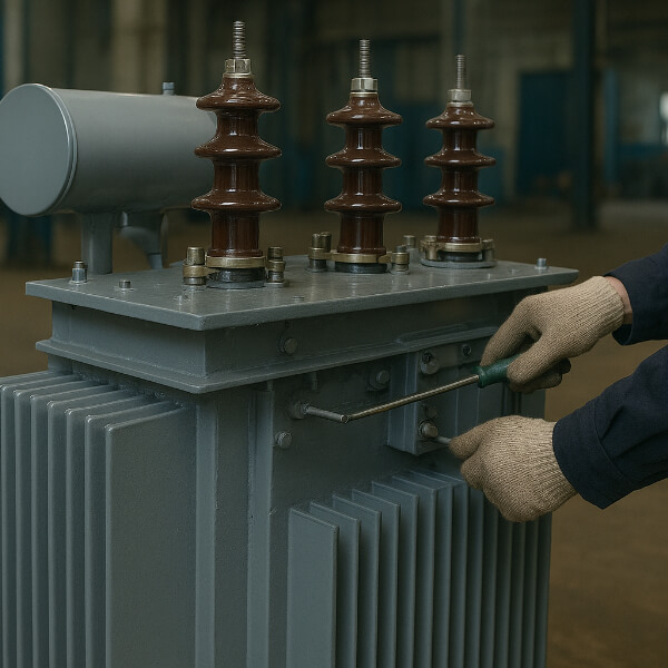
Tanks must be welded to standard with post-weld inspections, leak tests and corrosion protection treatments.
Cooling equipment (radiators, fans, pumps) should be sized with redundancy for critical applications and include simple, maintainable controls.
Use high-quality bushings, seals and gaskets to preserve dielectric integrity; plan for easy replacement.
Testing is the final verification before a transformer is trusted in the field.
Routine tests: turns ratio, winding resistance, insulation resistance, power factor, and dielectric tests.
Type/Design tests: temperature rise, short-circuit withstand, impulse withstand, noise and vibration assessments as required by standards.
Oil tests and DGA: check oil properties and dissolved gas levels to create an operational baseline.
Mechanical tests: leak and pressure trials, tap changer operation, and mechanical fit checks.
Offer witnessed Factory Acceptance Tests (FAT) with a complete documentation package to the buyer.
Sustained quality demands systems, not one-offs.
Implement ISO-level quality processes: calibrated equipment, material certificates, and process records.
Track serial numbers, lot numbers and test reports to enable root cause analysis if issues arise.
Maintain a formal non-conformance and corrective action program to learn from failures and close loops on improvements.
Damage during transit and poor commissioning are frequent causes of premature failure.
Design packaging to absorb shock and prevent moisture ingress. Protect bushings and fragile accessories.
On arrival, verify oil level, perform quick dielectric and moisture checks, and repeat critical tests if transit was long or the package was damaged.
Commission under controlled conditions: staged energization, baseline DGA, temperature monitoring and verification of protection settings.
A durable transformer remains durable only if cared for.
Offer recommended spares (bushings, fan assemblies, tap-changer parts) and clear maintenance schedules.
Provide condition monitoring options: periodic DGA, online gas sensors, temperature logging and Partial Discharge (PD) surveys.
Supply operator training and clear O&M manuals — human error during operation is a major risk.
Future-proof your designs.
Account for increased harmonics and non-sinusoidal waveforms from inverters — adjust copper sizing, cooling and insulation to cope.
For extreme environments, specify higher thermal classes, additional corrosion protection and consider ester fluids in fire-sensitive locations.
Make control interfaces and sensor ports modular so upgrades (sensors, smarter OLTC control) are straightforward.

Document real operating duty and conservative thermal margins.
Specify premium core steel and copper; require material certificates.
Enforce CNC winding, tension control, and mechanical bracing standards.
Vacuum dry and, if required, VPI impregnate windings.
Degas and filter oil to acceptance criteria; fill under vacuum.
Perform comprehensive electrical, mechanical and oil tests; provide FAT.
Maintain traceability and calibration records; run CAPA.
Provide commissioning support, spares list and condition monitoring plan.
High-quality, long-lasting transformers are the result of deliberate design choices, disciplined manufacturing, stringent testing and continued lifecycle care. Transformer manufacturers that bake robustness into materials, processes and documentation — and that provide clear after-sales support — deliver units that minimize total cost of ownership and reliably serve the grid for decades.