Hot Keywords:
- All
- Product Name
- Product Keyword
- Product Model
- Product Summary
- Product Description
- Multi Field Search

Views: 0 Author: Welldone power Publish Time: 2026-07-16 Origin: Site


A transformer nameplate is not a label. It is a compressed engineering contract — every number on it represents a decision someone made about how this machine will behave under your specific grid conditions. Read it wrong, or specify it wrong, and the consequences arrive not as a gradual decline but as a sudden, expensive failure.
This guide walks through the seven parameters that actually determine whether a distribution transformer will integrate cleanly into your system or cause problems from the moment it is energized. For each one, we go beyond the textbook definition and address the question that matters in practice: what happens if this number is wrong?
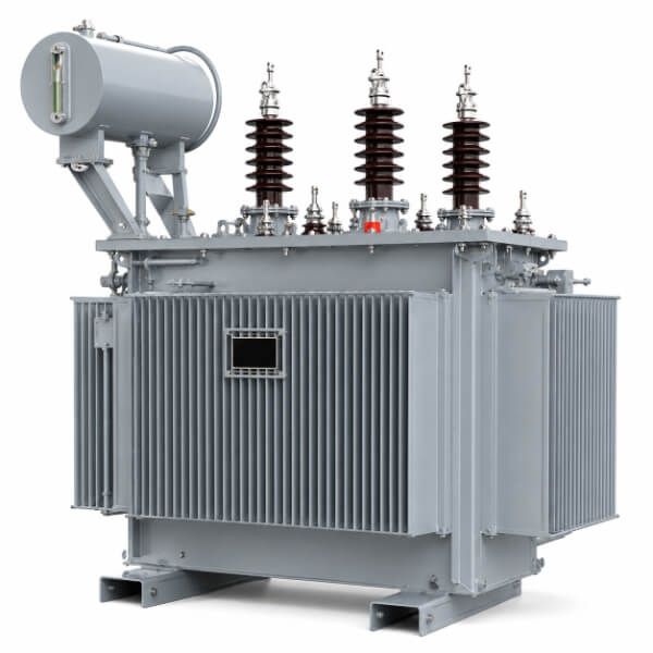
The rated capacity, expressed in kilovolt-amperes (kVA), is the maximum apparent power the transformer can deliver continuously without exceeding its insulation temperature rise limit, under specified ambient conditions.
Transformers are rated in kVA, not kW, because the windings heat based on current — and current depends on apparent power, not real power. A 500 kVA transformer loaded at 500 kW with unity power factor runs at the same winding temperature as the same unit delivering 300 kW at 0.6 power factor. In both cases, the current is identical. The transformer does not know or care how much of that current is doing useful work versus magnetizing motors.
Undersizing is the obvious failure mode — the transformer overheats, insulation ages at an accelerated rate, and the unit fails prematurely. What is less obvious is the mathematics of insulation aging. Insulation paper life follows a variant of the Arrhenius equation: every 6°C increase in hot-spot temperature above the design value approximately halves the remaining insulation life. A transformer chronically loaded 15% above its kVA rating may see a 10–12°C hot-spot elevation — cutting a 30-year design life to under 10 years.
Oversizing is the more insidious and common error. An oversized transformer is not “safe” — it is wasteful. No-load (core) losses are constant: they are paid every hour the transformer is energized, regardless of load. A 1000 kVA unit loaded at 200 kVA burns the same core losses as one loaded at 900 kVA, but delivers only a fraction of the useful work. On a 20-year total-cost-of-ownership basis, the wasted energy cost of a grossly oversized transformer can exceed the purchase price of the unit itself.
Specify the kVA rating based on a realistic diversified load profile — not the arithmetic sum of every connected device. Apply a demand factor (typically 0.6–0.8 for commercial, 0.5–0.7 for residential) to the connected load, then add 15–25% growth margin. Cross-check against the IEC 60076 preferred rating series (100, 160, 200, 250, 315, 400, 500, 630, 800, 1000, 1250, 1600, 2000, 2500 kVA) to ensure you are specifying a standard size — non-standard ratings carry cost and lead-time penalties for zero technical benefit.
The voltage ratio, typically written as 11000/433 V or 22/0.433 kV, defines the rated primary (high-voltage) and secondary (low-voltage) winding voltages.
Here is the detail that catches every first-time buyer: the secondary voltage on the nameplate is the no-load voltage — the terminal voltage measured with zero load connected. Under load, the internal impedance of the transformer causes a voltage drop. At full load and typical power factor (0.8), this drop is approximately equal to the impedance percentage.
This is why a transformer designed for a 415 V utilization voltage carries 433 V on the nameplate. The engineering logic:
No-load secondary voltage: 433 V
Voltage drop at full load: ~18 V (≈ 4% of 433 V)
Actual voltage at full load:415 V ← matches the system utilization voltage
If the nameplate stated 415 V as the secondary voltage, the transformer would deliver approximately 398 V at full load — below the acceptable tolerance for most equipment. The 433 V figure is not a manufacturing error; it is a deliberate design offset that compensates for the transformer’s own voltage regulation.
Mismatching the primary voltage is catastrophic. Connecting a transformer designed for 11 kV to a 33 kV system does not merely cause poor performance — the insulation system is not rated for 33 kV, and the core saturates at three times the designed flux density. The result is immediate, violent failure: enormous magnetizing inrush current, core overheating within seconds, and likely internal flashover.
Ignoring tap range is the subtler error. Most distribution transformers carry an off-circuit tap changer with a range of ±2 × 2.5% or ±5%. These taps adjust the effective turns ratio on the high-voltage winding, allowing the secondary voltage to be fine-tuned for the actual primary voltage at the installation point. If your feeder voltage runs persistently high (say, 11.5 kV on an 11 kV system), selecting the appropriate tap brings the secondary voltage back into range. Failing to set the tap correctly means the transformer delivers out-of-spec voltage throughout its service life — and every connected motor, lighting circuit, and electronic device pays the price.
Always specify the actual measured primary voltage at the installation point — not the nominal system voltage. If the feeder runs at 10.8 kV, say so. The manufacturer will set the tap changer to the appropriate position during final assembly. Also specify the tap range required: ±5% in 2.5% steps is standard for most distribution applications, but areas with known voltage fluctuations may require ±10%.
The vector group — for example, Dyn11 — is a compact code following IEC 60076-1 conventions that describes two things: how the windings are connected (delta, star, or zigzag) and the phase angle displacement between primary and secondary line voltages.
Breaking down Dyn11:
D — High-voltage winding connected in delta (triangle)
y — Low-voltage winding connected in star (wye)
n — Neutral point of the LV star winding is brought out as a terminal
11 — LV line voltage lags HV line voltage by 30 degrees (clock position 11)
Dyn11 is the de facto standard for distribution transformers in IEC-standardized markets, and for good engineering reasons:
Harmonic suppression: The delta-connected HV winding provides a closed path for triplen harmonics (3rd, 9th, 15th). These circulate within the delta and do not propagate into the upstream network, keeping the grid cleaner.
Neutral availability: The star-connected LV winding with brought-out neutral supports the four-wire system (three phases + neutral) that delivers both 230 V phase-to-neutral and 400 V phase-to-phase — the standard distribution configuration.
Zero-sequence isolation: The delta-star combination blocks zero-sequence current from passing between primary and secondary, preventing ground fault currents on the LV side from reflecting into the HV protection system.
This is where most nameplate guides stop — at “Dyn11 is standard.” But the engineering decision is more nuanced:
Yyn0 is used in some legacy systems, particularly in older North American and Chinese rural networks. The HV winding is star-connected with an accessible neutral, and the LV winding is also star-connected with zero phase displacement. The advantage is simplicity — same connection on both sides, no phase shift. The critical disadvantage: the Yyn0 configuration cannot suppress triplen harmonics because there is no delta winding to provide a closed path. Third-harmonic currents circulate in the system, and the neutral point can experience significant voltage displacement under unbalanced load. A Yyn0 transformer feeding unbalanced loads will show measurable neutral-to-earth voltage — a safety concern and a power quality problem.
Yzn11 (also written as Yzn or star-zigzag) is used specifically in areas with high lightning incidence or severe unbalanced load conditions. The zigzag-connected LV winding has inherently low zero-sequence impedance — meaning it can carry unbalanced phase and neutral currents with minimal voltage shift. This makes Yzn transformers particularly suited to rural distribution where single-phase loads dominate and phase balancing is poor. The trade-off: the zigzag winding requires approximately 15% more conductor material than a conventional star winding, increasing cost.
Paralleling mismatch: Two transformers with different vector groups (say, one Dyn11 and one Dyn1) cannot be paralleled. The 60° phase displacement between their secondary voltages creates a circulating current limited only by the transformer impedances — typically resulting in current magnitudes approaching the full short-circuit current. The transformers will trip on differential protection or, if protection fails, burn.
Neutral instability: Specifying Yyn0 where Dyn11 is needed creates a transformer that cannot handle unbalanced loads without significant neutral shift. In a residential area with predominantly single-phase loads, the neutral point drifts, causing some customers to see overvoltage and others undervoltage — damaging connected equipment.
Always specify the vector group explicitly in the tender — do not leave it to the manufacturer’s default. For new installations in IEC markets, Dyn11 is correct. For replacement of existing units, read the nameplate of the old transformer and match the vector group exactly — a mismatch will prevent paralleling during the switchover. For areas with severe load imbalance or high lightning, consider Yzn11 and discuss the trade-offs with the manufacturer’s engineering team.
The impedance voltage — typically 4% to 6% for distribution transformers — is the percentage of rated voltage that must be applied to the primary winding to circulate rated current through the secondary when the secondary terminals are shorted.
Impedance is the rare parameter that pulls in opposite directions depending on what you care about:
| Higher impedance | Lower impedance |
| Lower short-circuit current → easier on breakers and busbars | Higher short-circuit current → stresses downstream equipment |
| Poorer voltage regulation → bigger voltage drop under load | Better voltage regulation → tighter voltage control |
| More reactive power consumed by the transformer | Less reactive power consumed |
A distribution transformer with too low an impedance (say, 3% when the system was designed for 5%) will deliver a short-circuit current that exceeds the interrupting rating of downstream protective devices. The circuit breaker may fail to clear the fault — or worse, rupture during the attempt.
A transformer with too high an impedance will cause unacceptable voltage sag during motor starting. A 75 kW induction motor across-the-line starter can draw 6–7× full-load current for several seconds. On a high-impedance transformer, this inrush translates into a voltage dip of 15–20% — enough to drop out contactors, reset PLCs, and stall the motor itself.
Specify the impedance voltage with a tight tolerance (typically ±5% of the nominal value, not the broader ±10% allowed by IEC 60076). If the transformer will operate in parallel with existing units, the impedance values must match within ±3% — otherwise, load sharing will be disproportionate and one unit will overload while the other runs below capacity.
The cooling class code — for example, ONAN (Oil Natural, Air Natural) — describes how heat is removed from the transformer.
Common codes for distribution transformers:
ONAN — Oil circulates by natural convection; heat dissipates through radiators by natural air flow. The standard for most distribution units up to ~2500 kVA.
ONAF — Oil circulates naturally; fans force air over the radiators. The fans typically add 25–33% to the ONAN rating.
Specifying ONAF when the installation environment has no reliable power supply for cooling fans means the transformer operates at its lower ONAN rating — which may be insufficient for the load. Conversely, specifying ONAN for a unit that actually needs ONAF capacity means the transformer runs hotter than designed, with the same insulation-life-halving penalty described above.
A subtler issue: ONAF cooling class assumes the fans are maintained and operational. A transformer with non-functioning fans (failed motors, broken wiring, thermal switches tripped) silently derates to its ONAN capacity. If the load exceeds this derated value, the transformer fails — and the failure mode is thermal, meaning it develops slowly enough to evade protection relays until insulation breaks down.
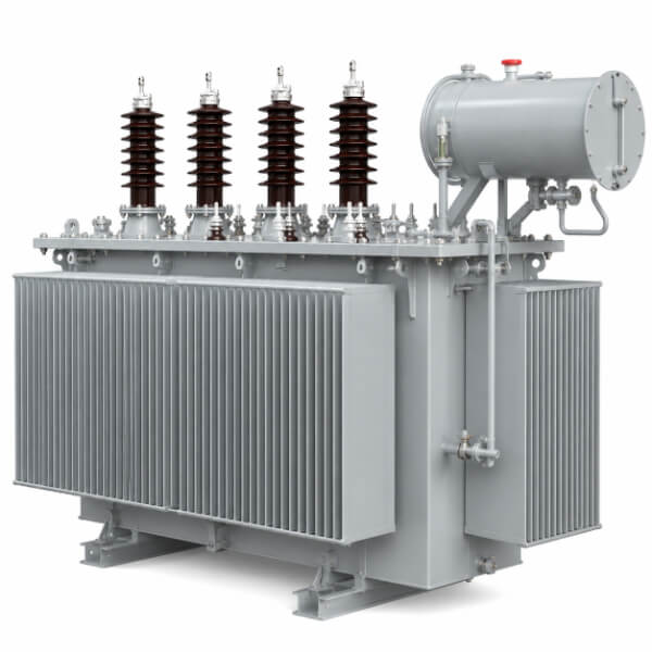
The insulation level is written as a pair of values, for example, LI75AC35 for a 12 kV class winding:
LI75 — Lightning impulse withstand voltage of 75 kV peak (1.2/50 μs standard waveshape)
AC35 — Power frequency withstand voltage of 35 kV RMS applied for 60 seconds
The lightning impulse level determines whether the transformer survives a direct or nearby lightning strike. The AC withstand level determines whether it survives switching surges and sustained overvoltage conditions. These are different failure mechanisms — a transformer can have excellent impulse withstand but poor AC withstand, or vice versa.
Match the insulation level to the system’s overvoltage exposure, not just the nominal voltage. In areas with overhead lines and frequent lightning, specify the higher impulse category (for example, LI95AC35 instead of LI75AC35 for a 12 kV system). In underground cable networks with no lightning exposure, the standard level is sufficient — and specifying higher levels wastes money on insulation that the application does not need.
The temperature rise limit — typically 65°C for oil-immersed distribution transformers — is the maximum allowable temperature increase of the winding above the ambient air temperature under rated continuous load.
The 65°C rise figure is only meaningful in conjunction with the ambient temperature assumption. IEC 60076 specifies standard ambient conditions as:
Maximum ambient air temperature: 40°C
Maximum monthly average: 30°C
Maximum yearly average: 20°C
A transformer with a 65°C rise rating operating at 40°C ambient runs its windings at 105°C. But the same transformer installed in a location where ambient regularly reaches 50°C — common in the Middle East, parts of Africa, and tropical Asia — sees windings at 115°C, well beyond the design point. The insulation aging rate doubles for every 6°C above the design hot-spot temperature.
If your installation location has ambient conditions that exceed the IEC standard, specify this in the tender. The manufacturer will either derate the kVA rating (a 500 kVA unit may be supplied as a “450 kVA at 50°C ambient” rating) or upgrade the cooling system to maintain the 65°C rise at the elevated ambient.
A distribution transformer nameplate is the most concentrated engineering document in the power distribution chain. Seven numbers — capacity, voltage ratio, vector group, impedance, cooling class, insulation level, and temperature rise — collectively determine whether the transformer will integrate seamlessly into your grid or become a source of recurring problems.
The cost of reading these parameters correctly is zero. The cost of getting them wrong — measured in failed transformers, unplanned outages, damaged downstream equipment, and shortened service life — is always higher than anyone budgets for.
At Welldone, every nameplate parameter is the output of a deliberate design calculation, not a default value copied from a template. When you specify a Welldone distribution transformer, the engineering team works with you to verify that each parameter matches your system conditions — because a nameplate that does not match the grid it serves is just an expensive piece of metal.


