Hot Keywords:
- All
- Product Name
- Product Keyword
- Product Model
- Product Summary
- Product Description
- Multi Field Search

Views: 0 Author: Welldone power Publish Time: 2026-07-22 Origin: Site


When you look at a transmission tower, the hanging strings of discs or sleek polymer rods rarely catch your eye. Yet these components decide whether a megawatt of electricity reaches a factory or fizzles out in a blinding flash. Engineers don’t select insulators from a catalog based on voltage alone. The real selection process is a balancing act between raw physics and gritty field conditions—where rain, dust, bird droppings, and even factory smoke conspire to defeat insulation.
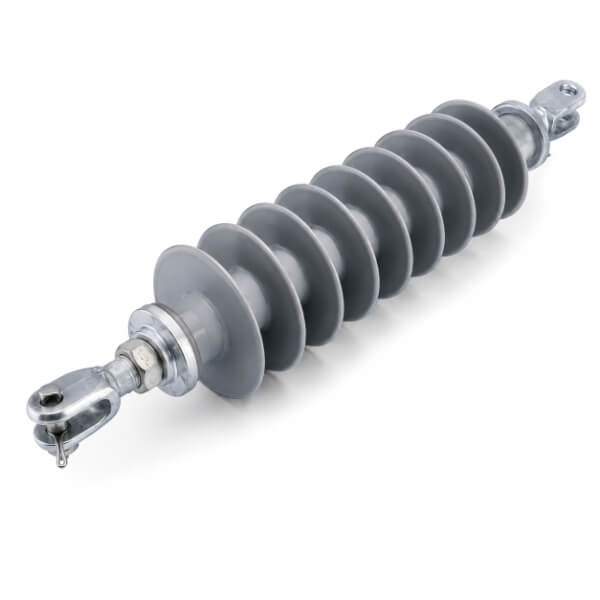
The power system imposes a set of absolute thresholds. If an insulator fails these, no amount of environmental protection can save it.
An insulator must handle three distinct voltage regimes simultaneously:
Continuous operating voltage – the phase-to-ground stress that never stops.
Switching surges – transient overvoltages from circuit breaker operations, which can reach 2–3 times the normal level.
Lightning impulses – steep-front surges that test the dielectric strength in microseconds.
The key design rule: flashover voltage must always be lower than puncture voltage. In plain terms, the insulator is allowed to spark over along its surface (which self-restores), but it must never break down through the solid material—because that is permanent failure. Industry practice demands a puncture-to-flashover margin of at least 1.5× for porcelain and toughened glass.
For high-voltage AC systems, the internal loss angle (tan δ) of the insulating body matters more than many realize. Excessive loss generates internal heat, accelerating aging and potentially leading to thermal runaway. Meanwhile, sharp edges on metal fittings—ball sockets, pin ends—create corona discharge. Besides wasting energy, corona produces radio-frequency interference that can disturb nearby communication lines. Manufacturers now routinely simulate electric field distribution to round off high-stress points.
Every insulator supports not just its own weight but also:
Conductor tension (span length × weight per meter)
Ice accretion (can multiply load by 3–5×)
Wind pressure (especially in typhoon-prone coasts)
Short-circuit electromagnetic forces (during faults, conductors jerk violently)
The codified safety factor for suspension insulators is 4.0—meaning the certified mechanical failing load is four times the maximum routine working tension. For long-span river crossings, that factor can rise to 5.0. But static strength alone isn’t enough. The steel caps and pins undergo millions of low-amplitude vibration cycles from aeolian wind, so fatigue resistance is a separate, mandatory test.
Sudden summer thunderstorms drench hot porcelain, creating severe thermal gradients. Materials must survive this without cracking (tested by rapid hot-cold water immersion). Additionally, when a flashover does occur, the power-follow current generates an electric arc. The insulator surface—whether glazed ceramic or polymer housing—must resist ablation. Glass insulators, interestingly, have a “self-shattering” feature: internal tension causes faulty units to shatter visibly, giving linemen a clear visual flag for replacement.
The same insulator that performs flawlessly in a dry, temperate laboratory can fail within months in a coastal industrial zone. Environmental adaptation is often the decisive factor.
Contamination accumulates on insulator surfaces: salt spray from oceans, cement dust, chemical exhaust, or agricultural fertilizers. When humidity rises—not even rain, just fog or dew—the contaminant dissolves into a conductive electrolyte, triggering pollution flashover at voltages far below the dry withstand level.
The universal countermeasure is specific creepage distance – the total leakage path length divided by the system voltage. Heavy pollution zones (e.g., near petrochemical plants) demand up to 43 mm/kV (line-to-line), compared to 20 mm/kV for clean rural areas. But geometry matters equally. Alternating large and small sheds (umbrella-shaped ribs) prevents continuous water films from bridging the gaps, and deep under-rib grooves interrupt tracking paths.
For polymer (silicone rubber) insulators, hydrophobicity – the ability to repel water – provides an extra defense. Even when covered with dust, the silicone’s low surface energy transfers its water-repellent property to the contamination layer, so moisture beads up instead of spreading into a conductive film.
Above 1,000 meters, thinner air lowers the breakdown voltage. The correction rule is roughly 1% reduction in withstand voltage per 100 m elevation. At 3,000 m (common in the Andes or Tibetan plateau), the required impulse withstand level must be boosted by nearly 30%. Designers achieve this by adding extra elements or increasing the overall stack height, not by changing material chemistry.
Freezing rain coats insulators in ice, forming icicles that connect adjacent sheds. This dramatically shortens the effective creepage path. Worst of all, when melting begins, the water film on ice becomes highly conductive. Special anti-icing sheds feature wider gaps between ribs, preventing icicle bridging. Some ultra-cold regions also use semi-conducting glazing that generates slight surface heat to inhibit ice formation.
Desert/wind-blown sand – abrasive particles erode the protective glaze or polymer sheath. Porcelain needs a glaze thickness above 400 microns, and polymer housings require enhanced tear strength.
Intense UV (high altitude or tropical sun) – breaks down polymer chains in silicones. Qualified materials pass accelerated aging tests (≥1000 hours of xenon-arc exposure) with anti-UV additives.
Fungal growth – in humid rainforests, mold secretes organic acids that corrode metal fittings. Galvanization with zinc or Dacromet coating, plus sealed cement joints between metal and ceramic, is mandatory.
Bird droppings – a well-known nuisance. Bird guano deposits create a conductive path, often triggering flashover during light drizzle. Utilities install deterrent spires or extra creepage margins, but the fundamental solution is to specify insulators with higher pollution tolerance than the local zone requires.
In heavy industrial belts, sulfur dioxide and ammonia gases dissolve in rain to form weak acids that attack the zinc coating and the Portland cement used to bond metal caps to ceramic bodies. Waterproof sealants and thicker galvanized layers (≥85 µm) are standard for such sites.
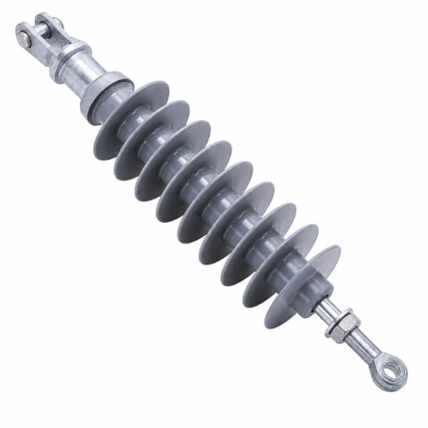
No single material wins everywhere. Here is the honest trade-off table that utility engineers debate in project meetings:
| Material | Strength | Achilles’ Heel | Key Mitigation |
| Porcelain | Proven century-long track record; excellent arc resistance; no aging mechanism | Heavy; low pollution performance; needs periodic “zero-value” detection (internal cracks) | Use anti-fog glaze profiles; increase shed count for contaminated areas |
| Toughened Glass | Zero-value defects visible instantly (shattered units); high dielectric strength; uniform quality | Fragile during transport; residual self-breakage rate (~0.02–0.04%) | Specify proof stress ≥140 MPa on surface compression; ensure shattered units retain enough residual strength to avoid conductor drop |
| Silicone Composite | Lightweight (1/10th of porcelain); outstanding hydrophobicity; eliminates routine cleaning | Vulnerable to UV aging, bird pecking, and interfacial delamination between core rod and housing | Require 100% dielectric integrity testing on the rod-sheath interface; demand brittle-fracture safety margins (core rod strain ≤ 20% of ultimate) |
To wrap up, the entire selection philosophy boils down to three interconnected alignments:
Electrical matching – The insulator’s impulse and power-frequency ratings must bracket the maximum credible overvoltage of the specific grid node, including resonant effects from series compensation or long cable sections.
Mechanical matching – The assembly (string or post) must tolerate the 1-in-100-year extreme weather scenario – simultaneous maximum wind and full ice load – with a safety margin that accounts for manufacturing scatter.
Environmental matching – This is the most dynamic variable. Rather than applying a national standard blindly, smart operators correlate creepage distance with local 30-year contamination records (ESDD/NSDD measurements) and adjust for microclimates around valleys, coastlines, and factories.
Insulators are not commodities. A bulk purchase based solely on price and rated voltage invites catastrophic outages that cost millions in lost industrial production and public safety risks. The real expertise lies in reading the fine print of pollution maps, wind rose diagrams, and ice-load charts—then demanding designs that over-deliver in the one parameter that matters most: long-term survival in the place they are actually installed.


