Hot Keywords:
- All
- Product Name
- Product Keyword
- Product Model
- Product Summary
- Product Description
- Multi Field Search

Views: 0 Author: Welldone power Publish Time: 2026-10-21 Origin: Site


A distribution transformer was built for one job: step voltage down and push power out. EV charging and rooftop solar now ask it to do the opposite twice a day. Meeting that demand is a specification problem, not a marketing one — and it changes what you should order.
For a century the design assumption was benign: power entered the high-voltage winding, left through the low-voltage winding, and never came back. The rating, the tap, the cooling, the protection — every one of those was sized against a single direction of flow and a gentle, human-shaped daily curve. That assumption is now false on millions of feeders.
Two technologies arrived at the same transformer from opposite ends of the day. Electric vehicles plug in where people live, mostly in the evening, and pull hard. Rooftop photovoltaics sit on the same roofs and push power back up the feeder at midday, when nobody is home to use it. A unit engineered for a calm one-way slope now has to survive a forward surge after sunset and a reverse surge at noon — and the two stresses land on the same windings hours apart.
This is not a future scenario. Berkeley Lab's open tracking dataset counted roughly 5.3 million distributed solar and storage systems installed in the United States through the end of 2025. EV adoption is climbing on the same residential feeders. The transformer in the green pad-mounted box at the end of the street is where both trends collide.
The comfortable old planning method — take last year's peak, add 2–3% growth, buy with margin — breaks the moment EVs appear. A residential distribution transformer typically loafs through most of the day at around 35% of rating. Add three home chargers and the picture changes.
In a widely cited load study, a 25 kVA transformer serving three houses ran at roughly 8 kW typical load, peaking near 22 kW before EVs. With three vehicles quick-charging at about 3.8 kW each and plugging in around a 6 p.m. mean, the same transformer exceeded 130% of rating for roughly an hour. Short-term overload of that kind is tolerated by the thermal design — but it is the kind of event that, repeated nightly across a neighborhood, quietly consumes insulation life.
Scale the penetration and the numbers get worse, not better. Power-flow simulations at 50% EV adoption on radial low-voltage networks show voltage drops beyond −8.2% and cable loading past 120% of thermal limit during the evening peak, with transformer loading above 1.2 per-unit in dense pockets. A separate study of German grids found that uncontrolled "greedy" or purely price-chasing charging strategies drove rural-transformer overloads above 250% on peak evenings, while a balanced strategy that shifted charging into the low-load night window removed most of the violation.
The mechanism is simple and stubborn: uncontrolled home charging stacks directly on top of the existing residential evening peak. The transformer's worst hour of the day just got a second, larger occupant.
Rooftop solar inverts the transformer's reason for existing. For hours around midday, distributed generation behind a single pad-mounted unit can exceed the local section load. Current enters the low-voltage winding and leaves through the high-voltage winding — the unit becomes a step-up source where the feeder expected a sink.
Copper does not care about direction. Load loss stays proportional to current squared whether current enters the high-voltage or low-voltage side, and core loss is unchanged. That is the reassuring half, and it is also why reverse flow hides so well: a transformer in reverse duty can pass its ratio test, its winding-resistance test, and even a dissolved-gas analysis with nothing to report.
Everything built on a voltage-drop assumption cares very much. On a radial feeder, voltage falls as current moves away from the substation, and the tap is set to compensate for that drop. Reverse the current and the same impedance produces a voltage rise instead. A tap that was fighting a 3% forward drop starts adding voltage to a network that already has too much. In one documented case, a 500 kVA pad-mounted unit with its tap left at +2.5% above nominal — set years earlier to fight forward drop on a longer circuit — pushed the secondary above the utility voltage band on a clear April afternoon, with the unit barely loaded. The fix cost nothing in copper: a tap change and a re-issued nameplate.
The overvoltage is not marginal. Modeling of high-penetration PV feeders shows secondary voltage climbing to 1.095 per-unit at the feeder end in worst-case scenarios, blowing past the ±6% band many utilities allow. At 30–50% penetration, smart inverters begin displacing conventional voltage-support capacitors entirely — the network's old tools stop applying in the old way.
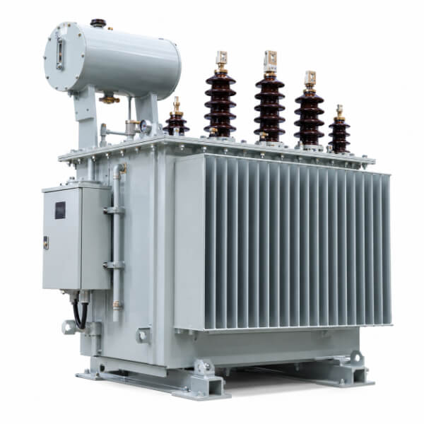
Here is the part that makes this a transformer-specification problem rather than two separate ones. The EV load and the PV export do not arrive together — they arrive at opposite ends of the day, and each one stresses the unit the other does not.
A transformer sized for the old one-way evening peak now runs a near-rated-current export window at midday and a forward peak after sunset. Insulation ages on the compound of hottest-spot temperature and time, and two daily peaks give it twice the heat-soak windows. Worse, the voltage-regulation need flips sign between those windows: the tap that rescues the evening under-voltage is the tap that causes the midday over-voltage. A fixed tap cannot serve both. Without storage or controlled charging to flatten the curve, the unit is caught between a voltage band it cannot satisfy in both directions.
This is the "duck curve" collapse happening inside a single green box: a deep midday reverse trough and a steep evening forward ramp, twelve hours apart, on the same iron.
The answer is not "buy a bigger transformer." Oversizing wastes capital and, on a reverse-flow feeder, a larger unit can actually worsen voltage rise. The real answer is a different specification — five capabilities a one-direction unit was never asked to prove.
1. Adaptive, not fixed, voltage regulation. A unit on a two-way feeder needs an on-load tap changer (OLTC) or an actively controlled voltage-regulating scheme, set with awareness of both flow directions. Mechanical OLTCs react slowly and can mis-track the rapid transients of passing clouds on a solar feeder; solid-state versions built on IGBTs or thyristors respond in milliseconds and eliminate arcing wear. The tap range and control logic must be specified for both the forward-undervoltage and reverse-overvoltage cases, not the forward one alone.
2. Bidirectional power-flow tolerance as a declared design case. Reverse flow is no longer an edge condition to be survived — it is a scheduled operating mode. The specification should state the expected reverse power magnitude and duration and require the unit to carry it within thermal and regulatory limits. Protection coordination (directional overcurrent, earth-fault sensing) must be reviewed for current that can flow either way.
3. Harmonic and power-electronic duty. Both EV chargers and PV inverters are power-electronic interfaces. They inject harmonics and switch at high frequency, and a feeder dense with them presents a distortion spectrum a legacy transformer rarely saw. The unit needs harmonic-withstand margin in its loss budget and, where the standard applies, design consistent with IEEE 519 limits at the point of common coupling. Core and conductor selection that minimizes eddy and stray-loss heating under non-sinusoidal load pays off here.
4. A data interface, not just a nameplate. A future-ready unit is a sensor as much as a converter. Monitoring of winding temperature, oil level and pressure on liquid-filled designs, and partial-discharge activity (measured per IEC 60270, with a well-built unit typically showing well below 10 pC at rated voltage) turns a passive asset into an early-warning device. The communication standard that matters is IEC 61850 — MMS for vertical reporting into SCADA or an ADMS, GOOSE for sub-cycle protection messaging, and the 7-420 extension for distributed-energy-resource logical nodes — backed by IEC 62351 for cybersecurity. A unit that cannot report its own loading cannot be managed in a bidirectional grid.
5. Thermal margin for double-peaking. Because the unit now sees two daily stress windows, specify against the combined daily energy and the hottest-spot temperature across both, not against the single legacy peak. F-class insulation with a 65 °C average winding rise is a common mainstream choice that buys margin; the specification should state the expected duty cycle explicitly so the thermal design is verified against it.
Dimension | Conventional unit (one-way) | Future-ready unit (bidirectional) |
Voltage regulation | Fixed tap, forward-drop compensation | OLTC / controlled, both directions |
Flow direction assumed | One-way (substation → load) | Two-way, reverse declared as design case |
Harmonic duty | Sinusoidal load assumed | Power-electronic margin (IEEE 519 context) |
Monitoring | Nameplate only | Winding temp, PD, oil, IEC 61850 out |
Protection | Non-directional | Directional overcurrent / earth fault |
Thermal basis | Single evening peak | Double daily peak, hottest-spot both |
State the flow directions. Declare expected forward peak load and expected reverse export (magnitude, hours per day). A unit specified only for forward flow will surprise you at noon.
Require an OLTC or active regulation sized for both signs of voltage error, and ask the manufacturer to show the tap range against your feeder's measured voltage profile in both windows.
Specify the harmonic environment — number and type of chargers/inverters, expected THD at the point of common coupling — and require the loss budget to hold under it.
Mandate a monitoring and communication package: IEC 61850 MMS/GOOSE, partial-discharge and temperature sensing, IEC 62351 security. Ask for the communication conformance as part of factory acceptance, not as a field afterthought.
Define the duty cycle for thermal rating as the combined two-peak day, and require the hottest-spot temperature calculation against it.
Confirm interconnection alignment: the unit's protection and grounding must sit inside the utility's DER interconnection rules (in IEC markets, the IEEE 1547 family is the reference for DER behavior; match the transformer's grounding and protection to it).
Q: Will adding rooftop solar damage my existing distribution transformer?A: Not directly — copper loss is direction-independent and core loss is unchanged, so reverse flow alone does not overheat the windings. The real risk is voltage: a tap set to fight forward drop will push the secondary above band during midday export, and repeated over-voltage stresses insulation and trips inverters. The fix is usually a tap and nameplate change, verified against the two-way voltage profile.
Q: Why can't I just buy a bigger transformer to solve EV and PV loads?A: Oversizing wastes capital, and on a reverse-flow feeder a larger unit can worsen midday voltage rise. The constraint is usually voltage regulation and harmonic duty, not raw kVA. The correct response is adaptive voltage control, bidirectional-rated protection, and monitoring — not brute capacity.
Q: What communication standard does a grid-ready transformer need?A: IEC 61850 is the substation-automation baseline — MMS for reporting into SCADA/ADMS, GOOSE for fast protection messaging, and the 7-420 extension for distributed-energy-resource nodes — with IEC 62351 for security. Cellular or remote secondary substations may also need IEC 60870-5-104.
Q: Do EV chargers and solar inverters hurt the transformer through harmonics?A: Both are power-electronic, so they inject harmonics a legacy sinusoidal-load design did not budget for. The unit needs harmonic-withstand margin in its loss design and, where applicable, performance consistent with IEEE 519 at the point of common coupling. It is a real loss and heating consideration, not a paperwork one.
Q: What does IEEE 1547 have to do with the transformer specification?A: IEEE 1547 governs how distributed energy resources interconnect — abnormal conditions, power quality, and anti-islanding behavior the transformer must live with. The transformer's grounding and protection coordination should be matched to the utility's 1547-based interconnection rules so the unit behaves correctly under both flow directions.
The distribution transformer did not change. The network around it did — it became two-way, and it peaks twice. A unit specified for one direction will pass every routine test and still fail the feeder: over-voltage at noon from rooftop export, overload after sunset from EV charging, and no data path to see either coming. The fix is a specification that declares reverse flow as a design case, regulates voltage in both directions, budgets for power-electronic harmonics, and reports its own condition over IEC 61850. Get that specification right and the same green box at the end of the street serves the next decade of load instead of fighting it.


